
Specifications


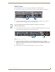
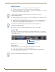


Table Of Contents
- Vision2 Operation/Reference Guide
- Table of Contents
- Overview
- Wiring and Device Connections
- Installation
- Accessing Servers
- Master Service
- Live (MPEG) Service
- Live (WMV) Service
- Reflector Service
- DVB Service
- Archive Service
- Thumbnail Editor
- Thumbnail Viewer
- Producer Service
- Record Service

Installation
25
Vision
2
Operation/Reference Guide
WMV Solution
The following steps show you how to setup a typical configuration for the WMV Solution:
1. Connect the power supply to the power connector on the rear of the Vision
2
Master server (FIG. 15).
2. Connect an RJ-45 LAN cable to LAN port one on the back of the Vision
2
Master server. Connect the
other end of the cable to a Gigabit port on a layer 3 network switch.
3. Connect an RJ-45 LAN cable to LAN port one on the back of the WMV appliance (FIG. 16). Connect the
other end of the cable to Gigabit ports on a layer 3 network switch.
4. Connect breakout cables to the HD-15 ports on the WMV capture cards at the rear of the WMV
appliances. Connect the other end of the cables to a Windows Media Video (WMV) source. The breakout
cable provides connections for Composite, S-Video, and Component video, in addition to balanced and
unbalanced stereo audio.
5. Repeat steps 3 and 4 for each additional WMV appliance you have in your solution.
FIG. 15 Vision
2
Master server (rear-view)
LAN ports
Power connector
To prevent multicast traffic from flooding your network, use LAN port 2 as the Vision
2
client side multicast interface.
FIG. 16 WMV appliance (rear panel)
LAN ports
Power
connector