
Specifications

Installation
16
RADIA Lighting Control System
Configuring and Connecting AxLink
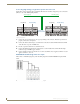
On all AMX Lighting controllers, DIP switch SW1 sets the AxLink device number. The device number is
determined by the value of all the switch position settings. The following table shows the SW1 DIP switch
positions and their values. The device number assignment range is 1 through 255.
1. Power off the enclosure unit at the breaker panel.
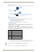
2. Locate the SW1 DIP switch (AxLink ADDRESS) on the controller circuit card and set the device number
using the values shown in the proceeding table.
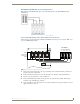
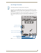
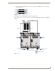
3. Connect the four-pin AxLink male connector into the four-pin female AxLink connector on the controller
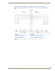
circuit card. FIG. 20 shows how to wire the AxLink connector to a Central Controller system.
4. Apply power to the controller module at the breaker panel.
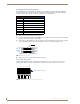
Connecting dry closures
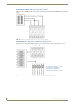
AMX Lighting controller modules contain eight connections for dry contact closures, and one common
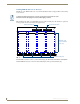
reference point. FIG. 21 shows the standard wiring configuration for the 9-pin dry closure connector.
SW1 DIP switch setting values for AxLink
Position Value
11
22
34
48
516
632
764
8 128
FIG. 20
AxLink wiring diagram
FIG. 21 9-pin dry closure connector (standard configuration)
Central ControllerAxLink connector
+12V
AXP/TX
AXM/RX
GND
+12V
AXP
AXM
GND
(optional)
C
O
M
1 2 3 4 5 6 7 8
9-pin Dry Closure Connector