
Specifications

Installation
15
RADIA Lighting Control System
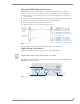
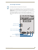
4. Connect the four-pin PROlink male connector to the four-pin female PROlink connector on the AMX
Lighting controller.
5. Apply power to the AMX Lighting controller at the breaker panel.
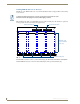
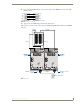
FIG. 19 shows an example of how to interconnect two AMX Lighting RDD-DM4 controllers and a PROlink
wall panel.
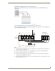
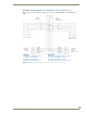
FIG. 18 PROlink wiring diagram
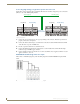
FIG. 19 PROlink configuration sample
Radia PROlink connectorPROlink wall panel
+12V
PR+
PR-
GND
+12V
PR+
PR-
GND
Neutral Neutral
HOT (1) HOT (2)
PROlink connector
RDD-DM4
(pack 2)
PROlink
PRO-DP8 wall panel
RDD-DM4
(pack 1)
PROlink connector
(orange)
(orange)