
Specifications

Installation
14
RADIA Lighting Control System
Module Connections
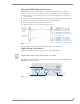
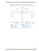
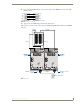
When connecting a dimming/switching module to a AMX Lighting controller, connect as shown in FIG. 17.
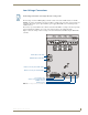
Green Status LED Indicator
When you apply power to the AMX Lighting Control System, the green status LED notes its conditions:
It is on full when power is applied to the control module.
It blinks on and off when AxLink communication is present.
It is off after default initialization is complete.
The LED indicator is located near the dry closure connector on the control module.
Red Status LED Indicators
The red LED's function is to indicate level. LED brightness increases as signal level increases from zero to
100. The LED indicator is located above each external load connector jack on the control module.
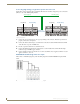
Configuring and Connecting PROlink
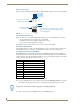
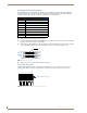
On all AMX Lighting controllers, DIP switch SW2 sets the PROlink pack number. The pack number is
determined by the value of all the switch position settings. The following table shows the SW2 DIP switch
positions and their values. The pack number assignment range is 1 through 10. The lighting system will not
work if you assign a pack number outside of the range.
1. Power off the AMX Lighting enclosure at the breaker panel.
2. Locate the SW2 DIP switch on the controller circuit card (marked PROLINK ADDRESS), and set the
pack number using the values shown in the proceeding table. The pack number must be 1 to 10.
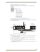
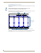
3. FIG. 18 shows how to wire the PROlink connector to a PROlink wall panel.
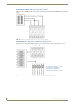
FIG. 17 Module connection to a con-troller card
SW2 DIP Switch Setting Values for PROlink
Position Value
11
22
34
48
5n/a
6n/a
7n/a
8 All lights on
Pin 4 (GND)
Pin 3 (RLY)
Pin 2 (DIM)
Pin 1 (+12V)
3 (-)
1 (+)
The 4-pin plug from the module connects to a 4-pin
connector on the controller module with the black
cover facing upwards.
4-pin module connector on
AMX Lighting controller
4-pin plug from RDM
controller module
Assign pack 1 for all communications, diagnostics, and feedback response.