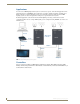
Operation/Reference Guide RADIA Lighting Control System Controllers / Modules / Cards Lighting Controls Last Revised: 5/23/2012
AMX Limited Warranty and Disclaimer This Limited Warranty and Disclaimer extends only to products purchased directly from AMX or an AMX Authorized Partner which include AMX Dealers, Distributors, VIP’s or other AMX authorized entity.
Table of Contents Table of Contents Introduction ........................................................................................................1 Features.................................................................................................................... 1 Applications .............................................................................................................. 2 Controllers ...........................................................................................
Table of Contents ii RADIA Lighting Control System
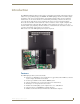
Introduction Introduction The AMX Radia Lighting Control System™ employs a dual-platform programming architecture that supports both the Axcess programming language and PROlink. The AMX Lighting product line is modular by design, and includes a wide variety of integrated dimmer control modules, dimmer modules, and also switch/relay modules.
Introduction Applications You can use the AMX Lighting Control System for commercial, corporate, and residential applications. The dual-platform Axcess and PROlink control architecture can address virtually any number of lighting zones. Entire residential or commercial lighting systems can be manually controlled or fully automated. AMX Lighting systems can also be integrated into existing Axcess presentation/control systems.
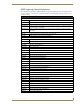
Introduction AMX Lighting Control Equipment The following table lists all of the AMX Lighting Control System equipment. Refer to the installation sheets for these enclosures, control modules, and dimmer modules for detailed wiring drawings, application notes, and specifications.
Introduction AMX Lighting Control Equipment (Cont.) Dimmer modules (Cont.
Installation Installation Space Requirements AMX Lighting control installations require very little space. Enclosures are the main concern. All enclosures are mounted flush, on a vertical surface and must have a minimum clearance of 12" (304.8 mm) above and below to allow for air circulation. Physical dimensions for each enclosure are described in the Installation section. Conduit Conduit runs depend on the enclosures you use and their AMX Lighting modules.
Installation Enclosure Dimensions RDA-ENC2, -ENC4, and -ENC6 Enclosure and Dimensions FIG. 4 shows the dimensions for the RDA-ENC2, RDA-ENC4, and RDA-ENC6 enclosures. RDA-ENC2 RDA-ENC4 0.75" (19.05 mm) RDA-ENC6 6.0" (152.4 mm) Top View Side View (for all enclosures) Internal View 12.0" (304.8 mm) Bottom View 6.0" (152.4 mm) 12.0" (304.8 mm) 18.0" (457.2 mm) FIG. 4 RDA-ENC2, RDA-ENC4, and RDA-ENC6 enclosure dimensions RDA-ENC6B and RDA-ENC12B Enclosures and Dimensions FIG.
Installation Mounting AMX Lighting Enclosures AMX Lighting enclosures must be mounted on a vertical surface with a minimum of 12" (304.8 mm) clearance above and below the enclosure. FIG. 6 shows the centerline reference points and dimensions. 1. Remove the front cover by removing the screws at the bottom of the enclosure; two tabs suspend the cover from the top. 2. Position the enclosure on the wall so that it is level, with the high-voltage terminals of the unit at the top. 3.
Installation Connecting High-Voltage, Single-Phase Input Power and Loads Follow these steps to wire high-voltage (120 VAC, 240 VAC, and 277 VAC), single-phase power connections (FIG. 8) to any of the AMX Lighting modules. Ground (green) Hot (black) Ground (green) Neutral (white) Hot (black) Neutral (white) to Enclosure ground terminal FIG. 8 RDD-DM4 and RDD-DM6 (as examples only) high-voltage, single-phase power connections for line input (hot), neutral, and ground. 1.
Installation RDA-ENC6B 120/240 VAC Line Input (Single Phase) FIG. 10 shows a 120/240 VAC single-phase (3 W + G) wiring diagram for the RDA-ENC6B line input terminal block. 1 2a 2b 3 FIG. 10 RDA-ENC6B 120/240 VAC single-phase (3 W + G) wiring diagram Connecting High-Voltage, Three-Phase Input Power and Loads Follow these steps to wire high-voltage (120 VAC and 240 VAC), three-phase power connections (FIG. 11) to any of the AMX Lighting modules.
Installation RDA-ENC6B 120/208 VAC Line Input (Three Phase) FIG. 12 shows a 120/208 VAC three-phase (4 W + G) wiring diagram for the RDA-ENC6B line input terminal block. 1 2a 2b 3 FIG. 12 RDA-ENC6B 120/208 VAC three-phase (4 W + G) wiring diagram RDA-ENC6B Three Phase Line Input Connector Reference FIG. 13 shows a sample RDA-ENC6 three phase (4 W + G) line input connector and dimmer references.
Installation RDA-ENC6 and RDA-ENC12 Power Distribution and Line Input References FIG. 14 shows the power distribution and line input references for the RDA-ENC6 and RDA-ENC12 line inputs. RDA-ENC6 Line input 1 feeds dimmers 1 and 4 Line input 2a feeds dimmer 5 Line input 2b feeds dimmer 2 Line input 3 feeds dimmers 3 and 6 RDA-ENC12 Line input 1 feeds dimmers 1 and 4, 7 and 10 Line input 2a feeds dimmer 5 and 11 Line input 2b feeds dimmer 2 and 8 Line input 3 feeds dimmers 3 and 6, 9 and 12 FIG.
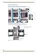
Installation Installing RDM Modules Into an Enclosure Installing any of the RDM modules is an easy task. The individual modules are shipped with the four mounting screws enclosed. To prevent possible personal injury or death, cut off power to the enclosure at the breaker box before attempting to install any AMX Lighting modules. FIG. 15 illustrates the inside of an RDA-ENC6 enclosure and the mounting slots. The modules are positioned in the appropriate slot and secured using the supplied screws.
Installation Low-Voltage Connections All low-voltage connections must comply with Class 2 wiring codes. The low-voltage area in the AMX Lighting controllers contain connections and DIP switches for AxLink, PROlink, dry closures, and module jack connectors. On the controller cards, low-voltage power for the board is supplied either by line power, optional auxiliary power supply (RDA-PSM), or the +12 VDC pin on the AxLink connector.
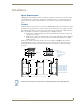
Installation Module Connections When connecting a dimming/switching module to a AMX Lighting controller, connect as shown in FIG. 17. Pin 4 (GND) Pin 3 (RLY) Pin 2 (DIM) Pin 1 (+12V) 4-pin module connector on AMX Lighting controller 3 (-) 1 (+) 4-pin plug from RDM controller module The 4-pin plug from the module connects to a 4-pin connector on the controller module with the black cover facing upwards. FIG.
Installation 4. Connect the four-pin PROlink male connector to the four-pin female PROlink connector on the AMX Lighting controller. +12V PR+ PRGND +12V PR+ PRGND PROlink wall panel Radia PROlink connector FIG. 18 PROlink wiring diagram 5. Apply power to the AMX Lighting controller at the breaker panel. FIG. 19 shows an example of how to interconnect two AMX Lighting RDD-DM4 controllers and a PROlink wall panel.
Installation Configuring and Connecting AxLink On all AMX Lighting controllers, DIP switch SW1 sets the AxLink device number. The device number is determined by the value of all the switch position settings. The following table shows the SW1 DIP switch positions and their values. The device number assignment range is 1 through 255. SW1 DIP switch setting values for AxLink Position Value 1 1 2 2 3 4 4 8 5 16 6 32 7 64 8 128 1. Power off the enclosure unit at the breaker panel. 2.
Installation Each contact closure connection (1 through 8) is pre-programmed with a default preset. The following table shows the default presets for each contact closure.
Installation External Power The following table lists the modules that use most of the operating power a AMX Lighting control module can supply. They may require extra power from the AxLink connection, or an external power supply connected to the control module or module(s) when using multiple modules.
Compatible Ballast Information Compatible Ballast Information This section contains descriptions and manufacturer information on AC-controlled magnetic ballasts, ACcontrolled electronic ballasts, DC-controlled electronic ballasts, and ballast interfaces that are compatible with the AMX Lighting Control System. The ballasts listed in this section have been reported to AMX by other parties to be compatible with AMX Lighting dimming systems.
Compatible Ballast Information DC-Controlled Electronic Ballasts (4-Wire Ballasts) The DC-controlled Electronic Ballasts track a 0-10 or 0-12 VDC channel for dimming and an AC switch channel for on/off. This ballast design is better than magnetic, but many stop dimming at about 20% brightness. That's fine for energy management and secondary lighting zones, but not for primary lighting that requires precision, low-level dimming control. The following table lists compatible DC-controlled electronic ballasts.
Glossary Glossary Air Gap Switch - A relay or mechanical switch that physically separates a load from the power feed, resulting in an air gap between the contacts. An air gap is a deliberate and noticeable space or disruption in a circuit causing an open condition. AxLink - A four-wire data bus used to transmit and receive data from the AxLink Central Controller to any of 255 devices on the system.
Glossary Electronic Transformer - A transformer that reduces the voltage output when the primary voltage of the transformer is reduced. This causes the secondary output of the transformer to reduce its voltage through electronic means. Electronic transformers should be specifically designed for standard dimming. Some electronic transformers are not dimmable or exhibit poor dimming performance. Enclosure - The UL-approved box into which Radia Lighting control cards, modules, and accessories are installed.
Glossary Power Consumption Rating - An amount of energy used by a device to perform its function at maximum load. Radia Lighting devices have power consumption ratings expressed in milliamps (mA). Radia Lighting controllers provide this power to operate the modules and can also get more power from external power supplies. Power Rating - Ratings expressing the maximum load capacity of a module, dimmer, or switch. Radia Lighting power ratings are based on UL testing and approvals.
AMX. All rights reserved. AMX and the AMX logo are registered trademarks of AMX. AMX reserves the right to alter specifications without notice at any time. ©2012 5/12 It’s Your World - Take Control™ 3000 RESEARCH DRIVE, RICHARDSON, TX 75082 USA • 800.222.0193 • 469.624.8000 • 469-624-7153 fax • 800.932.6993 technical support • www.amx.