instruction manual Radia Lighting Control System Controllers, Modules, and Cards Lighting Controls
AMX Limited Warranty and Disclaimer AMX Corporation warrants its products to be free of defects in material and workmanship under normal use for three (3) years from the date of purchase from AMX Corporation, with the following exceptions: • Electroluminescent and LCD Control Panels are warranted for three (3) years, except for the display and touch overlay components that are warranted for a period of one (1) year.
Table of Contents Table of Contents Introduction ...............................................................................................................1 Features ............................................................................................................................ 1 Applications ....................................................................................................................... 2 Controllers ..................................................................
Table of Contents Glossary ..................................................................................................................
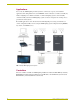
Introduction Introduction The AMX Radia Lighting Control SystemTM employs a dual-platform programming architecture that supports both the Axcess programming language and PROlink. The AMX Lighting product line is modular by design, and includes a wide variety of integrated dimmer control modules, dimmer modules, and also switch/relay modules.
Introduction Applications You can use the AMX Lighting Control System for commercial, corporate, and residential applications. The dual-platform Axcess and PROlink control architecture can address virtually any number of lighting zones. Entire residential or commercial lighting systems can be manually controlled or fully automated. AMX Lighting systems can also be integrated into existing Axcess presentation/control systems.
Introduction AMX Lighting Control Equipment The following table lists all of the AMX Lighting Control System equipment. Refer to the installation sheets for these enclosures, control modules, and dimmer modules for detailed wiring drawings, application notes, and specifications.
Introduction AMX Lighting Control Equipment (Cont.) Dimmer modules (Cont.
Installation Installation Space Requirements AMX Lighting control installations require very little space. Enclosures are the main concern. All enclosures are mounted flush, on a vertical surface and must have a minimum clearance of 12" (304.8 mm) above and below to allow for air circulation. Physical dimensions for each enclosure are described in the Installation section. Conduit Conduit runs depend on the enclosures you use and their AMX Lighting modules.
Installation Install the control modules according to local and National Electrical Code (NEC) regulations. Enclosure Dimensions RDA-ENC2, -ENC4, and -ENC6 enclosure and dimensions FIG. 4 shows the dimensions for the RDA-ENC2, RDA-ENC4, and RDA-ENC6 enclosures. RDA-ENC2 RDA-ENC4 0.75" (19.05 mm) RDA-ENC6 6.0" (152.4 mm) Top View Side View (for all enclosures) Internal View 12.0" (304.8 mm) Bottom View 6.0" (152.4 mm) 12.0" (304.8 mm) 18.0" (457.2 mm) FIG.
Installation Mounting AMX Lighting Enclosures AMX Lighting enclosures must be mounted on a vertical surface with a minimum of 12" (304.8 mm) clearance above and below the enclosure. FIG. 6 shows the centerline reference points and dimensions. 1. Remove the front cover by removing the screws at the bottom of the enclosure; two tabs suspend the cover from the top. 2. Position the enclosure on the wall so that it is level, with the high-voltage terminals of the unit at the top. 3.
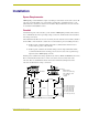
Installation Connecting high-voltage, single-phase input power and loads Follow these steps to wire high-voltage (120 VAC, 240 VAC, and 277 VAC), single-phase power connections (FIG. 8) to any of the AMX Lighting modules. Ground (green) Hot (black) Ground (green) Hot (black) Neutral (white) Neutral (white) to Enclosure ground terminal FIG. 8 RDD-DM4 and RDD-DM6 (as examples only) high-voltage, single-phase power connections for line input (hot), neutral, and ground. 1.
Installation RDA-ENC6B 120/240 VAC line input (single phase) FIG. 10 shows a 120/240 VAC single-phase (3 W + G) wiring diagram for the RDA-ENC6B line input terminal block. 1 2a 2b 3 FIG. 10 RDA-ENC6B 120/240 VAC single-phase (3 W + G) wiring diagram Connecting high-voltage, three-phase input power and loads Follow these steps to wire high-voltage (120 VAC and 240 VAC), three-phase power connections (FIG. 11) to any of the AMX Lighting modules.
Installation 5. Connect load lines from the electrical devices to the Load terminals. Load 1 applies to dimmer 1, Load 2 applies to dimmer 2, and so on. RDA-ENC6B 120/208 VAC line input (three phase) FIG. 12 shows a 120/208 VAC three-phase (4 W + G) wiring diagram for the RDA-ENC6B line input terminal block. 1 2a 2b 3 FIG. 12 RDA-ENC6B 120/208 VAC three-phase (4 W + G) wiring diagram RDA-ENC6B three phase line input connector reference FIG.
Installation RDA-ENC6 and RDA-ENC12 power distribution and line input references FIG. 14 shows the power distribution and line input references for the RDA-ENC6 and RDAENC12 line inputs. RDA-ENC6 Line input 1 feeds dimmers 1 and 4 Line input 2a feeds dimmer 5 Line input 2b feeds dimmer 2 Line input 3 feeds dimmers 3 and 6 RDA-ENC12 Line input 1 feeds dimmers 1 and 4, 7 and 10 Line input 2a feeds dimmer 5 and 11 Line input 2b feeds dimmer 2 and 8 Line input 3 feeds dimmers 3 and 6, 9 and 12 FIG.
Installation Neutral terminal block Ground terminal block Mounting screw holes for modules (4 per slot) Module mounting slots FIG. 15 Enclosure module mounting slots and mounting screw holes The RDA-ENC2 enclosure contains a ground-terminating lug. The RDA-ENC4, RDA-ENC6, RDA-ENC6B, and RDA-ENC12B enclosures contain a neutral terminating block and a groundterminating lug. Low-Voltage Connections All low-voltage connections must comply with Class 2 wiring codes.
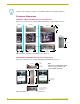
Installation AXlink address DIP switch PROlink address DIP switch Module connector jack and LED (CH5) Module connector jack and LED (CH6) Dry contact closures AXlink connector and status LED PROlink connector Auxiliary power in FIG. 16 Low-voltage connections and DIP switches Module connections When connecting a dimming/switching module to a AMX Lighting controller, connect as shown in FIG. 17.
Installation Green status LED indicator When you apply power to the AMX Lighting Control System, the green status LED notes its conditions: It is on full when power is applied to the control module. It blinks on and off when AXlink communication is present. It is off after default initialization is complete. The LED indicator is located near the dry closure connector on the control module. Red status LED indicators The red LED's function is to indicate level.
Installation +12V +12V PR+ PR- PR+ PR- GND GND PROlink wall panel Radia PROlink connector FIG. 18 PROlink wiring diagram 5. Apply power to the AMX Lighting controller at the breaker panel. FIG. 19 shows an example of how to interconnect two AMX Lighting RDD-DM4 controllers and a PROlink wall panel. Neutral HOT (1) Neutral HOT (2) RDD-DM4 (pack 1) RDD-DM4 (pack 2) PROlink connector (orange) PROlink connector (orange) PROlink PRO-DP8 wall panel FIG.
Installation Configuring and connecting AXlink On all AMX Lighting controllers, DIP switch SW1 sets the AXlink device number. The device number is determined by the value of all the switch position settings. The following table shows the SW1 DIP switch positions and their values. The device number assignment range is 1 through 255. SW1 DIP switch setting values for AXlink Position Value 1 1 2 2 3 4 4 8 5 16 6 32 7 64 8 128 1. Power off the enclosure unit at the breaker panel. 2.
Installation 1 2 3 4 5 6 7 8 C O M 9-pin Dry Closure Connector FIG. 21 9-pin dry closure connector (standard configuration) Each contact closure connection (1 through 8) is pre-programmed with a default preset. The following table shows the default presets for each contact closure.
Installation 4. Power up the controller enclosure and wait for the controller's green status LED to go off after approximately 1 minute. 5. Using a non-conductive rod or wooden one-quarter inch dowel rod (approximately 12" long) press the RESET button located on the controller module circuit board. 6. At the breaker panel, remove power from the controller enclosure. 7. Remove the jumpers from the dry contact closure connector. 8. Reconnect the AXlink and PROlink connections. 9.
Compatible Ballast Information Compatible Ballast Information This section contains descriptions and manufacturer information on AC-controlled magnetic ballasts, AC-controlled electronic ballasts, DC-controlled electronic ballasts, and ballast interfaces that are compatible with the AMX Lighting Control System. The ballasts listed in this section have been reported to AMX by other parties to be compatible with AMX Lighting dimming systems.
Compatible Ballast Information DC-controlled electronic ballasts (4-wire ballasts) Manufacturer Style Model Volts AMX Lighting modules Advance Mark VII All models 120 RDM-HDC Advance Mark VII All models 277 RDM-HDC RDM-DC RDM-2DC RDM-3DC Lightolier PowerSpec HDF See Ballast interfaces Magnatek TRIAD Magnatek TRIAD B232SR277V20 277 RDM-HDC Motorola Helios M2-RN-T8-10C-120 120 RDM-HDC Motorola Helios M2-RN-T8-10C-277 277 RDM-HDC Prescolite Intelect PUV series 120 RDM-HDC
Glossary Glossary Air Gap Switch - A relay or mechanical switch that physically separates a load from the power feed, resulting in an air gap between the contacts. An air gap is a deliberate and noticeable space or disruption in a circuit causing an open condition. AXlink - A four-wire data bus used to transmit and receive data from the AXlink Central Controller to any of 255 devices on the system.
Glossary Control Current - The current used by a dimmer or switch to perform its function. Each Radia Lighting controller supplies this current to its control ports and each Radia Lighting module uses and requires this current in order to operate the dimmer or switch. Control Port - The four-pin connector on the Radia Lighting controller used for electrical control of the dimmer (or switch) is called the Control Port. All modules connect to a control port to operate.
Glossary Integrated Dimmer Module - A Radia Lighting device that contains both a six-channel master controller and dimmers on the same package. They will have a PROlink address and can be on AXlink. The RDD-DM4/ series and the RDD-DM6/ series are integrated dimmer modules, and they all take up two module spaces. Level Time - A Radia Lighting default parameter. Level time is the time it takes for a dimmer to reach its assigned level after receiving a level command.
Glossary Preset Fade Time - A Radia Lighting default parameter. The amount of time it takes for one preset to begin to fade out and another preset to completely fade in. Preset Ramping - The active preset can be ramped to a different level while retaining the proportions and integrity of the preset scene. A preset can be dimmed so that all levels are zero and recovered or brought to full brightness and the dimmed back down to the original settings.
Glossary Radia Lighting Control System 25
ARGENTINA • AUSTRALIA • BELGIUM • BRAZIL • CANADA • CHINA • ENGLAND • FRANCE • GERMANY • GREECE • HONG KONG • INDIA • INDONESIA • ITALY • JAPAN LEBANON • MALAYSIA • MEXICO • NETHERLANDS • NEW ZEALAND • PHILIPPINES • PORTUGAL • RUSSIA • SINGAPORE • SPAIN • SWITZERLAND • THAILAND • TURKEY • USA ATLANTA • BOSTON • CHICAGO • CLEVELAND • DALLAS • DENVER • INDIANAPOLIS • LOS ANGELES • MINNEAPOLIS • PHILADELPHIA • PHOENIX • PORTLAND • SPOKANE • TAMPA 3000 RESEARCH DRIVE, RICHARDSON, TX 75082 USA • 800.222.