
User`s manual


Chapter 5: Advanced Serverboard Setup
5-15
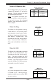
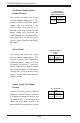
Power LED/Speaker/NMI
On the JDI header, pins 1-3 are for
a power LED and pins 4-7 are for the
speaker. See the table on the right
for speaker pin definitions.
Note: The speaker connector pins
are for use with an external speaker.
If you wish to use the onboard
speaker, you should close pins 6-7
with a jumper.
Speaker Connector Pin
Definitions (JD1)
Pin
Number
4
5
6
7
Function
+
Key
Definition
Red wire, Speaker data
No connection
Key
Speaker data
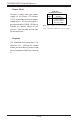
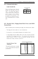
Wake-On-Ring
The Wake-On-Ring header is desig-
nated JWOR1. This function allows
your computer to receive and "wake-
up" by an incoming call to the mo-
dem when in suspend state. See
the table on the right for pin defini-
tions. You must have a Wake-On-
Ring card and cable to use this fea-
ture.
Wake-on-Ring
Pin Definitions
(JWOR1)
Pin
Number
1
2
Definition
Ground
Wake-up
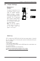
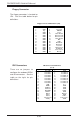
Wake-On-LAN
The Wake-On-LAN header is located
at JWOL on the motherboard. See
the table on the right for pin defini-
tions. You must enable the LAN
Wake-Up setting in BIOS to use this
function. (You must also have a LAN
card with a Wake-On-LAN connector
and cable to use this feature.)
Pin
Number
1
2
3
Definition
+5V Standby
Ground
Wake-up
Wake-On-LAN Pin
Definitions (JWOL)
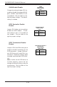
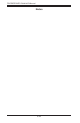
SMB
A System Management Bus header
is located at J22. Connect the ap-
propriate cable here to utilize SMB
on your system.
SMB Header
Pin Definitions (J22)
Pin
Number
1
2
3
4
Definition
Data
Ground
Clock
No Connection