
User`s manual
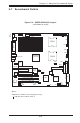

Chapter 5: Advanced Serverboard Setup
5-13
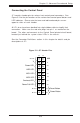
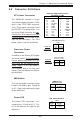
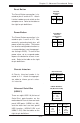
Power Button
The Power Button connection is lo-
cated on pins 1 and 2 of JF1. Mo-
mentarily contacting both pins will
power on/off the system. This button
can also be configured to function as
a suspend button (see the appropri-
ate setting in BIOS). To turn off the
power when set to suspend mode,
depress the button for at least 4 sec-
onds. Refer to the table on the right
for pin definitions.
Pin
Number
1
2
Definition
PW_ON
Ground
Power Button
Connector
Pin Definitions
(JF1)
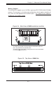
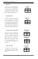
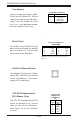
Universal Serial Bus
(USB0/1)
There are eight USB 2.0 (Universal
Serial Bus) ports/headers on the
motherboard. Four of them are back
panel USB ports (USB0-3 at J40),
and the other four are front panel
USB headers (USB4/5:JD3 and
USB6/7: JD2). See the tables on the
right for pin definitions.
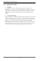
Reset Button
The Reset Button connection is lo-
cated on pins 3 and 4 of JF1. Attach
it to the hardware reset switch on the
computer case. Refer to the table on
the right for pin definitions.
Chassis Intrusion
A Chassis Intrusion header is lo-
cated at JL1. Attach the appropri-
ate cable to inform you of a chas-
sis intrusion.
Pin
Number
3
4
Definition
Reset
Ground
Reset Pin
Definitions
(JF1)
Pin
Number
1
2
Definition
Intrusion Input
Ground
Chassis Intrusion
Pin Definitions (JL1)
Pin# Definition
1 +5V
2 P0-
3 P0+
4 Ground
Pin
Number
2
4
6
8
10
Definition
+5V
PO-
PO+
Ground
Ground
Pin
Number
1
3
5
7
Definition
+5V
PO-
PO+
Ground
USB Pin Definitions
JD2 & JD3 (FP USB)
J40 (Back Panel USB)