
User`s manual


Chapter 3: System Interface
3-3
! Power Fail: Indicates a power supply module has failed. The re-
maining two power supply modules will take the load to keep the system
running continuously, but the failed module will need to be replaced. You
do not need to shut down the system to replace the failed module. Refer to
Chapter 6 for details on replacing the power supply module. This LED
should be off when the system is operating normally.
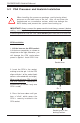
3-4 SCSI Drive Carrier LEDs
Each SCSI drive carrier has two LEDs.
! Green: When illuminated, the green LED on the front of the SCSI drive
carrier indicates drive activity. A connection to the SCSI SCA backplane
enables this LED to blink on and off when that particular drive is being
accessed.
! Red: A SAF-TE compliant backplane is needed to activate the red
LEDs, which indicate a drive failure. Please refer to Chapter 6 for instruc-
tions on replacing failed SCSI drives.
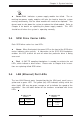
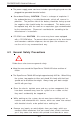
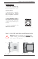
3-5 LAN (Ethernet) Port LEDs
The two LAN Ethernet ports (located beside the VGA port) each have a
yellow and a green LED. The yellow (left) LED indicates activity while the
other (right) LED may be green, orange or off to indicate the speed of the
connection. See the tables below for the functions associated with these
LEDs.
LED
Color
Off
Green
Orange
Definition
No Connection
100 MHz
1 GHz
Gb LAN Right LED
Indicator
LED
Color
Off
Yellow
Definition
Not Active
Active
Gb LAN Left LED
Indicator