
Installation guide


- 5 -
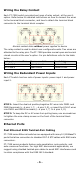
Wiring the Relay Contact
Each PT-7528 switch provides two types of relay output, at the user’s
option. Refer below for detailed instructions on how to connect the wires
to the terminal block connector, and how to attach the terminal block
connector to the terminal block receptor.
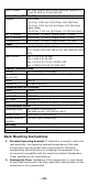
Normal contact state without power applied to device
The relay contact is used to detect user-configured events. Two wires are
attached to the relay pins. The PT-7528 provides normal open and normal
closed circuits at the user’s option. For pin definitions refer to the table
below:
Relay pin connection
Power on state
Event trigger
Pin 4 and 6
Closed circuit
Open circuit
Pin 8 and 6
Open circuit
Closed circuit
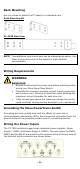
Wiring the Redundant Power Inputs
Each PT switch has two sets of power inputs: power input 1 and power
input 2.
STEP 1: Insert the dual set positive/negative DC wires into PWR1 and
PWR2 terminals (+ pins 1, 7; - pins 3, 9), or insert the L/N AC wires
into PWR1 and PWR2 terminals (L pins 1, 7; N pins 3, 9).
STEP 2: To keep the DC or AC wires from pulling loose, use a screwdriver
to tighten the wire-clamp screws on the front of the terminal block
connector.
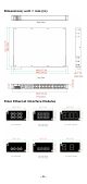
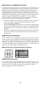
Ethernet Ports
Fast Ethernet RJ45 Twisted-Pair Cabling
PT-7528 series Ethernet switches are equipped with many 10/100BaseTX
ports that allow connection to standard CAT-5 STP cables with RJ45 male
connectors.
PT-7528 series products feature auto-negotiation, auto-polarity, and
auto-crossover functions. For high EMC environment applications, we
suggest using shielded twisted-pair cables to avoid EMC interference and
to retain compliance with the IEEE 1613 standard.