PT-7528 Series (24-Port Copper Models) Hardware Installation Guide Moxa PowerTrans Switch Second Edition, September 2014 2014 Moxa Inc. All rights reserved.
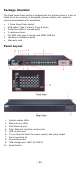
Package Checklist The Moxa PowerTrans switch is shipped with the following items. If any of these items are missing or damaged, please contact your customer service representative for assistance. • • • • • • • 1 Moxa PowerTrans switch USB cable (Type A male to Type B male) Protective caps for unused ports 2 rackmount ears CD-ROM with user’s manual and SNMP MIB file Hardware installation guide Warranty card Panel Layout 1. 2. 3. 4. 5. 6. 7. 8. 9. 10.
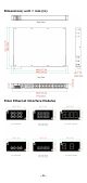
Dimensions; unit = mm (in) Fiber Ethernet Interface Modules -3-
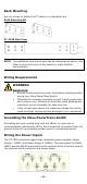
Rack Mounting Use six screws to attach the PT switch to a standard rack. Rack Mounting Kit PT-7528 Side View NOTE Two additional rack-mount ears can be ordered as an option. Use them to secure the rear of the chassis in high-vibration environments. Wiring Requirements WARNING Safety First! • Be sure to disconnect the power cord before installing and/or wiring your Moxa PowerTrans Switch. • Calculate the maximum possible current in each power wire and common wire.
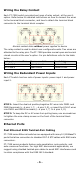
Wiring the Relay Contact Each PT-7528 switch provides two types of relay output, at the user’s option. Refer below for detailed instructions on how to connect the wires to the terminal block connector, and how to attach the terminal block connector to the terminal block receptor. Normal contact state without power applied to device The relay contact is used to detect user-configured events. Two wires are attached to the relay pins.
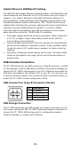
Gigabit Ethernet 1000BaseTX Cabling The IEEE 802.3ab Gigabit Ethernet standard defines 1000 Mbps Ethernet communications over distances of up to 100 meters using all 4 pairs in category 5 (or higher) balanced unshielded twisted-pair cabling. For wiring guidelines, system designers and integrators should refer to the Telecommunications Industry Association (TIA) TIA/EIA-568-A wiring standard that characterizes minimum cabling performance specifications required for proper Gigabit Ethernet operation.
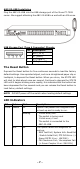
ABC-02-USB Installation Plug the ABC-02-USB into the USB storage port of the Moxa PT-7528 series. We suggest attaching the ABC-02-USB to a wall with an M4 screw. USB Storage Port (Type A Connector) Pinouts Pin 1 2 3 4 Description VCC (+5 V) D- (Data-) D+ (Data+) GND (Ground) The Reset Button Depress the Reset button for five continuous seconds to load the factory default settings. Use a pointed object, such as a straightened paper clip or toothpick, to depress the Reset button.
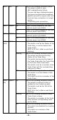
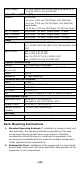
FAULT RED On PWR1 AMBER Off On Off PWR2 AMBER On Off MSTR/ GREEN HEAD On Blinking Off CPLR/ TAIL GREEN On Blinking Off One of the following situations exists: • The signal contact is open. • ABC Loading/Saving Failure. • The port has been disabled because the ingress multicast and broadcast packets exceed the ingress rate limit. • Incorrect loop connection in a single switch. • Invalid Ring port connection. The system is operating normally.
FAULT + MSTR/HEAD + CPLR/TAIL STATE + FAULT + MSTR/HEAD + CPLR/TAIL Ports GREEN 1 to 24 AMBER M1 Ports 1 to 4 GREEN AMBER Rotate ABC-02-USB is importing/exporting Blinking files. Sequentially Blinking 2 blinks per sec: The switch is being discovered/located by MXview.
Alarm Contact One relay output with current carrying capacity of 3 A @ 30 VDC or 3 A @ 240 VAC Optical Fiber (100BaseFX) Distance Multi-mode: 0 to 5 km, 1300 nm (50/125μm, 800 MHz*km) 0 to 4 km, 1300 nm (62.5/125μm, 500 MHz*km) Single-mode: 0 to 40 km, 1310 nm (9/125μm, 3.5 PS/(nm*km)) Min. TX Output Max.
3. 4. 5. Mechanical Loading: Mounting of the equipment on the rack should be such that a hazardous condition is not achieved due to uneven mechanical loading. Circuit Overloading: Consideration should be given to the connection of the equipment to the supply circuit and the effect that overloading of the circuits might have on overcurrent protection and supply wiring. Appropriate consideration of equipment nameplate ratings should be used when addressing this concern.