
Product specifications


Introduction
18
VG-Series Modero Touch Panels
VG-Series Modero Connectors
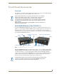
FIG. 1 shows the connectors on the VG-Series Modero panels.
Connecting and Using USB Input Devices
These panels can have up to two USB-capable input devices connected for use both on its different
firmware and TPD4 panel pages. These input devices can consist of a keyboard or mouse.
1. Insert the input device USB connectors into the appropriate USB connector on the panel.
2. Press the on-screen Reboot button (Protected Setup page) to save any changes and restart the panel.
3. After the panel splash-screen disappears:
If a USB mouse has been connected, a mouse cursor appears on the panel screen and its
location corresponds to the mouse cursor position sent by the external USB mouse.
If a USB keyboard has been connected, only on-screen keyboards and keypads will reflect any
external keystrokes sent from the external USB keyboard.
Cleaning the Touch Overlay
You should clean the touch screen overlay after each day’s use.
Always use clean cotton cloths and a spray bottle containing water.
FIG. 1 Connector layout on sample VG-Series Video Touch Panels (RGB connector available with RGB Kit)
RGB
AUDIO/VIDEO
RGB
ETHERNET
A
L
12VDC
PWR
PROGRAM
Stereo
Audio-Video from
Ethernet
Power
NXT VG-Series
rear panel of the base
NXD VG-Series
on left side panel
NXA-AVB/RGB
(CAT5)
Keyboard/Mouse
USB connectors (2)
Mini-USB
(Program Port)
(CAT5)
Composite/RGB
and pass-thru
control (CAT5)
connectors located on
connectors located
Output
USB-connected input devices are detected and recognized by the panel upon
connection. Refer to the Configuring and Using USB with a Virtual
Master section on page 95 for more information on using a USB connection.