Operation/Reference Guide NXR-ZGW-PRO NetLinx ZigBee Pro Gateway NXR-ZRP-PRO NetLinx ZigBee Pro Repeater Control System Accessories Last updated: 2/14/2012
AMX Limited Warranty and Disclaimer AMX warrants its products to be free of defects in material and workmanship under normal use for three (3) years from the date of purchase from AMX, with the following exceptions: • Electroluminescent and LCD Control Panels are warranted for three (3) years, except for the display and touch overlay components that are warranted for a period of one (1) year.
FCC Information (FCC Rules CFR 47, Part 15, Subpart C) This device complies with Part 15 of the FCC Rules and Industry Canada RSS 210, subject to the following two conditions: (1) this device may not cause harmful interference, and (2) this device must accept any interference received; including interference that may cause undesired operation.
Software License and Warranty Agreement LICENSE GRANT. AMX grants to Licensee the non-exclusive right to use the AMX Software in the manner described in this License. The AMX Software is licensed, not sold. This license does not grant Licensee the right to create derivative works of the AMX Software. The AMX Software consists of generally available programming and development software, product documentation, sample applications, tools and utilities, and miscellaneous technical information.
Table of Contents Table of Contents Overview ............................................................................................................1 NXR-ZGW-PRO NetLinx ZigBee Pro Gateway ........................................................ 1 NXR-ZRP-PRO NetLinx ZigBee Pro Repeater .......................................................... 3 How ZigBee works.................................................................................................... 4 Network Structure ....................
Table of Contents Configuration.......................................................................................................... 19 Configuration - Network IP Settings tab ....................................................................... 20 Bonjour Settings ....................................................................................................................... 21 Setting the IP Address ............................................................................................
Table of Contents BUFF DEVICE SIZE ..................................................................................................................35 ?VDEVS ...................................................................................................................................35 ?VDEVINFO EUI ......................................................................................................................35 Device Configuration .............................................................
Table of Contents iv NXR-ZGW-PRO NetLinx ZigBee Pro Gateway & NXR-ZRP-PRO NetLinx ZigBee Pro Repeater
Overview Overview The NXR-ZGW-PRO NetLinx ZigBee Pro Gateway (FG5791-11) is an Ethernet to ZigBee wireless gateway, designed as the center of a ZigBee Pro network. The NXR-ZGW-PRO features a 10/100BaseT, autonegotiating Ethernet port capable of Power over Ethernet (PoE), 16 Mbytes of Flash, 16 Mbytes of SDRAM, and a ZigBee Pro transceiver, and is controlled via a web server interface.
Overview NXR-ZGW-PRO Specifications (Cont.) Radio Specifications: • Frequency: IEEE 802.15.4 • Operating channels: 1 - 26 • Modulation technique: DSS • Output power: Region/country specific • Coverage area (N America): 165 feet (50.2m) IP Configuration: Static IP or DHCP client • DHCP default: DHCP/ZeroConf • Static IP default: 169.254.1.2 Communications: The NXR-ZGW-PRO communicates with a NetLinx master over TCP/IP encapsulating the ICSP protocol via a physical Ethernet connection.
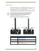
Overview NXR-ZRP-PRO NetLinx ZigBee Pro Repeater Antenna Antenna LEDs 2-pin 3.5mm PWR connector RESET Button Front Rear Antenna Mount FIG. 2 NXR-ZRP-PRO, front and rear NXR-ZRP-PRO Specifications Dimensions (HWD): • 906 x 2.500 x 3.424 (23.01 mm x 63.50 mm x 86.96 mm) • Depth does not include antenna Weight: • 0.25 lbs (113.39g) Power: 10.5 - 18 VDC; 13.5 (nominal operation voltage) Memory: • 1 Megabit external memory Radio Specifications: • Frequency: IEEE 802.15.
Overview NXR-ZRP-PRO Specifications (Cont.) Rear Components: Power connector Certifications: • 2-pin 3.5mm captive-wire PWR connector • FCC ID: CWU-ZRPPRO • IC: 5078B-ZRPPRO • CE • IEC/EN-60950 • ZigBee Certified Product Operating/Storage Environments: Included Accessories: • Operating Temperature: -30°C (-22°F) to 70°C (158°F) • Relative Humidity: 5% to 85% non-condensing; intended for indoor use only • NXR-ZRP Installation Guide (93-5791-04) • 2.4GHZ, MONO, RSMA, 3.5IN, 2.
Overview A device will always connect to a repeater or gateway based on the least depth of the connection, and then the best quality. For instance, given a choice between connecting to a repeater with two hops to a gateway or directly to a gateway, a device will always connect first to the gateway, even if the repeater has a slightly better connection. Devices cannot have children.
Overview 1 hop NXR-ZGW-PRO (Coordinator) NetLinx Master CAT5 Ethernet connection Mio R-4 FIG. 3 Single Extended PAN ID Network See Setting up a network section on page 13 for setting the Extended PAN ID and adding device EUI-64 Addresses. Multiple Gateway Installations A more commercial application of the NXR-ZGW-PRO is having multiple gateways and specific devices operating in close proximity of each other. Devices and repeaters of different networks can operate side-byside without interference.
Overview Patents This product employs or practices certain features and/or methods of one or more of the following patents: SIPCO, LLC U.S. Patent No. 7,103,511 U.S. Patent No. 6,914,893 U.S. Patent No. 7,697,492 FCC Warning Statement 1. This equipment complies with Part 15 of the FCC rules. Any changes or modifications not expressly approved by the manufacturer could void the user's authority to operate the equipment. 2.
Overview 8 NXR-ZGW-PRO NetLinx ZigBee Pro Gateway & NXR-ZRP-PRO NetLinx ZigBee Pro Repeater
Installation Installation Overview Several factors will help decide the best place to install NXR-ZGW-PRO and NXR-ZRP-PRO ZigBee Pro devices. Before installing, consider the following: Location and Antenna Direction The best location for NXR-ZGW-PRO and NXR-ZRP-PRO devices are usually in the center of your wireless network, with line of sight to all of your mobile devices. Try placing the antenna in a position that can best cover your wireless network.
Installation Connecting Power to the NXR-ZGW-PRO and NXR-ZRP-PRO The NXR-ZGW-PRO receives power via either PoE or 2-pin 3.5 mm mini-captive wire connection, while the NXR-ZRP-PRO only utilizes the 2-pin 3.5 mm mini-captive wire connection. When connecting both Ethernet and mini-captive wire connections to the NXR-ZGWPRO, PoE is overridden by the captive wire connection. PoE is only engaged if Ethernet is the only power source available to the device.
Installation Connecting the NXR-ZGW-PRO to a LAN Insert one end of the CAT5 Ethernet cable into the rear RJ-45 jack (see FIG. 1 on page 1) and connect the other end of the same cable to a master. See Mesh Network Arrangements section on page 5 for possible network configurations. Table-Top Installation Using the provided rubber pads, place one in each bottom corner of the device. These will prevent scratches on the table surface from the device casing.
Installation 12 NXR-ZGW-PRO NetLinx ZigBee Pro Gateway & NXR-ZRP-PRO NetLinx ZigBee Pro Repeater
Setting up a network Setting up a network Overview The NXR-ZGW-PRO and NXR-ZRP-PRO constitute the full Master-to-Device control solution via a ZigBee Pro wireless personal area network (PAN) using a mesh topology A variety of individual devices that can be controlled or be the source of input to the system are supported. This diagram in FIG. 7 shows MIO-R3 and MIO-R4 remotes connecting to a network via a NXR-ZGW gateway and multiple NXR-ZRP repeaters. FIG.
Setting up a network With an AMX system, the AMX NXR-ZGW-PRO fills that role. Multiple routers may be contained in a ZigBee network, and the routers must have a reliable power source to keep the network assembled. ZigBee messages travel through the network, attempting to minimize the hops between source and destination. Routers, including the Coordinator, share routing information and establish paths through the network, which is illustrated by the solid lines in FIG. 7.
Setting up a network If a repeater has been previously configured to a PAN, it must be reset to factory defaults before it can join a different PAN. This method may also be used if you do not want to go to each ZigBee compatible device to set the Extended PAN ID. However, once each device is set, the change must be made to the gateway itself. It may be necessary to cycle power on each device for them to come online. 10.
Setting up a network 16 NXR-ZGW-PRO NetLinx ZigBee Pro Gateway & NXR-ZRP-PRO NetLinx ZigBee Pro Repeater
NXR-ZGW-PRO Configuration Pages NXR-ZGW-PRO Configuration Pages Overview To access the NXR-ZGW on-board Configuration pages, enter the IP address of the NXR-ZGW-PRO into your web browser; the default IP configuration for the NXR-ZGW-PRO is DHCP/Zeroconf. Zeroconf will broadcast its Web services and allow connection. This broadcast may be viewed with any Zeroconf-enabled browser, such as NetLinx Studio or via the Bonjour plug-in for Internet Explorer and Safari.
NXR-ZGW-PRO Configuration Pages Summary of Gateway Settings Click the Summary button to access the Summary of Gateway Settings page. This page is also the initial access point for the Configuration Manager (FIG. 9). FIG. 9 Summary of Gateway Settings Page This page provides a quick summary of the current Gateway settings: Summary of Gateway Settings Options Version Firmware The version of the software running on the device. ZigBee Firmware The version of ZigBee software running on the device.
NXR-ZGW-PRO Configuration Pages Summary of Gateway Settings Page (Cont.) Pan Settings Wireless The state (Disabled/Enabled) of the wireless connection. Channel The ZigBee wireless channel used. Extended Pan ID The ZigBee personal area network ID used. Represented as "AZGXXXXX," where "XXXXX" are the last five numbers of the device's serial number. EUI The Extended Unique Identifier. This is the ZigBee equivalent of a MAC address, as it identifies the ZigBee hardware address for the gateway.
NXR-ZGW-PRO Configuration Pages Configuration - Network IP Settings tab Click the IP Settings tab of the Configuration page to access the Network IP Settings options. The options in this tab are used to set IP and DNS addresses. The IP address can be either a static or dynamic assignment. FIG. 11 Network IP Settings Page Configuration - Network IP Settings tab options IP Address IP • Dynamic: IP address and subnet mask are requested from the DHCP server. • Static: User provides IP address information.
NXR-ZGW-PRO Configuration Pages Bonjour Settings The Bonjour plug-in for Microsoft Internet Explorer 7 allows selection of information for individual Gateway devices within a Web browser. Zeroconf, also known as zero-configuration networking, allows users to locate networked computers, printers, and other equipment without knowing their IP address settings and without special serial cables or product-specific PC software.
NXR-ZGW-PRO Configuration Pages Configuration - NetLinx Settings tab Click the NetLinx Settings tab of the Configuration page to access the NetLinx Settings options. The options in this tab are used to view or edit the NetLinx settings for this gateway (FIG. 12): FIG. 12 NetLinx Settings Page Configuration - NetLinx Settings tab options Connection The mode in which the connection to the master is being made. Default: ID Mode. Mode The NetLinx mode being used.
NXR-ZGW-PRO Configuration Pages 6. Enter the IP address or the URL for the network Master in the IP/URL field (TCP URL and UDP URL only). 7. If the port used by the Master for its network connection needs to be changed, enter the new port number in the Master Port Number field (TCP URL only). 8. If connecting to a Master with security enabled, enter your username and password. 9. Click Accept to save any changes.
NXR-ZGW-PRO Configuration Pages Personal Area Network (PAN) Click the Pan button (FIG. 14) to access the tabbed Personal Area Network (PAN) page. FIG.
NXR-ZGW-PRO Configuration Pages Personal Area Network (PAN) Network tab options (Cont.) Encryption The encryption status of the network. Encryption is always on in a ZigBee network. Preshared Key When this parameter is enabled, all devices in the network must be commissioned to have the same preshared key to join the network. AES Key This is the user supplied preshared key value. It is a 32 digit hexadecimal key used for communications between the gateway and a device when the device is joining.
NXR-ZGW-PRO Configuration Pages 1. In the menu on the top of the NXR-ZGW Browser-Based Configuration Manager, select Network under the section Pan. 2. Click Accept. 3. Select the Connections tab; the repeater should appear on the gateway. 4. Click on the EUI-64 link to open the Device Details page. 5. In the Extended PAN ID field, enter the desired Extended PAN ID for the repeater within the network. This field defaults to the current network to which it is joined. 6. Click Update Settings. 7.
NXR-ZGW-PRO Configuration Pages Finding a Device’s EUI Address 1. In the menu on the top of the NXR-ZGW Browser-Based Configuration Manager, select Connections under the section Pan. 2. The EUI address is located in the Connections table under “EUI-64”. Click on the EUI address to open the PAN Device Details page for this device. (See FIG. 18) Finding the Device’s Description 1. In the menu on the top of the NXR-ZGW Browser-Based Configuration Manager, select Connections under the section Pan. 2.
NXR-ZGW-PRO Configuration Pages Personal Area Network (PAN) - Commission Devices tab options Auto Refresh: The current ability to automatically refresh the page to display new devices during the scanning period: either "On" or "Off". Refresh List: Manually refreshes the list of detected devices when pressed. EIU-64: The resource number of a particular detected device. Device Type: The type of device being commissioned. This information is provided by the device.
NXR-ZGW-PRO Configuration Pages Personal Area Network (PAN) - PAN Device Details Page From the Connections or the Commission Devices pages, clicking on a device’s EUI-64 number opens the Pan Device Details page (FIG. 18). FIG. 18 PAN Device Details Page Personal Area Network (PAN) - Pan Device Details page options Leave Network Connected Device This button removes a device from its PAN if clicked. • Device Type: The type of network device.
NXR-ZGW-PRO Configuration Pages PAN Device Details Page (Cont.) Device Information • Power Sources: All of the possible sources for power for the device, including mains electric power and rechargeable battery backup • Current Power: Current power source being used by the device. • Power Level: Amount of required power currently being received by the device. • Host F/W Version: Latest firmware version installed in the device. • Serial Number: The serial number of the device.
NXR-ZGW-PRO Configuration Pages Utilities Click the Utilities button (FIG. 19) to access the tabbed Utilities page. FIG.
NXR-ZGW-PRO Configuration Pages 2. Choose the device to be updated by its EUI-64 number. 3. Click the button next to the device’s EUI-64 number in the Allow Updates column. The page will automatically refresh, displaying the device’s new status. 4. Some devices cannot have their firmware update status changed; these devices will continue to read Off even after selecting to allow new updates. Allowing Firmware Updates To All Devices On a Network 1.
NXR-ZGW-PRO Configuration Pages Determining the Connection Status of a Device 1. In the menu on the top of the NXR-ZGW Browser-Based Configuration Manager, select Connection Log under the section Utilities. 2. The connection status of each device is located in the column Connection; the possible values are either Connected or Disconnected. The time in which the device either connected to the network or lost its connection is located under the column Time. Finding a Device’s EUI Address 1.
NXR-ZGW-PRO Configuration Pages Utilities - Traffic Log tab options (Cont.) Buffers Current The current number of buffers being used on the device. Threshold The maximum number of buffers available for use on the device. Exceeding this number will cause the device to fall offline. Max The maximum number of buffers that have been used since the last time the traffic log was cleared. Finding the Device’s ICSP Number 1.
Programming the NXR-ZGW-PRO Programming the NXR-ZGW-PRO Overview Some of the functionality of the NXR-ZGW-PRO may be handled using the application TPDesign4. Go to www.amx.com for the supporting documentation. The NXR-ZGW-PRO recognizes a select number of NetLinx Commands. SEND_COMMANDs Below is a list of SEND_COMMANDs accepted by the NXR-ZGW-PRO from NetLinx masters. To use these commands, establish a Telnet session from the PC to the NetLinx master.
Programming the NXR-ZGW-PRO 36 NXR-ZGW-PRO NetLinx ZigBee Pro Gateway & NXR-ZRP-PRO NetLinx ZigBee Pro Repeater
Device Configuration Device Configuration Changing the NXR-ZGW-PRO’s Device Number Use the NetLinx Studio application (available from www.amx.com) to change the device address on a NetLinx device. NetLinx Studio supports changing the Device Address information manually, or via ID Mode. Refer to the NetLinx Studio on-line help ("NetLinx Device Addressing" section) for instructions. Sending Firmware to The NXR-ZGW-PRO Use the NetLinx Studio application (available from www.amx.
AMX. All rights reserved. AMX and the AMX logo are registered trademarks of AMX. AMX reserves the right to alter specifications without notice at any time. ©2012 2/12 It’s Your World - Take Control™ 3000 RESEARCH DRIVE, RICHARDSON, TX 75082 USA • 800.222.0193 • 469.624.8000 • 469-624-7153 fax • 800.932.6993 technical support • www.amx.