
Installation guide

Installation Guide
NXR-ZRP-PRO NetLinx ZigBee Pro Repeater
Overview
The NXR-ZRP-PRO NetLinx ZigBee® Pro Repeater (FG5791-03) is a ZigBee
wireless repeater, designed to expand the range of a ZigBee Pro network. The
NXR-ZRP-PRO features one megabit of external memory and a ZigBee Pro
module. Through an NXR-ZGW-PRO gateway, it can be controlled via a web
server interface.
Specifications
Things To Consider Before Starting
Several factors will help decide the best place to install NXR-ZRP-PRO devices.
Before installing, consider the following:
Location and Antenna Direction
The best location for NXR-ZRP-PRO devices are usually in the center of your
wireless network, with line of sight to all of your mobile devices. Try to place the
antenna in a position that can best cover your wireless network. Normally, the
higher you place the antenna, the better performance you receive.
Note: For minimal interference, try to keep any installed NXR-ZRP-PRO at least
10’ (3.048m) from any WiFi access points.
NOTE (Mio R-3 or R-4 Users): Due to the wireless nature of the ZigBee
network, temporary interference (such as leaving a room or large objects
passing between the controller and its gateway device) may prevent a command
from reaching the NetLinx master. If this happens while increasing volume,
the master may receive the command to increase the volume but not the
command to stop increasing it. Therefore, programmers should consider
setting safeguards for volume control, either established volume limits or
timeouts with the NetLinx master or more interactive adjustment from the remote
(i.e., direct volume control), to prevent issues with lost commands.
NOTE: The NXR-ZRP-PRO NetLinx ZigBee Pro Repeater is optimized for the
ZigBee Pro 2007 protocol, and may not be connected to a ZigBee 2004 or 2006
network. For older ZigBee networks, the NXR-ZRP (FG5791-02) should be used
instead.
Connecting Power to the NXR-ZRP-PRO
The NXR-ZRP-PRO utilizes a 2-pin 3.5 mm mini-captive wire connection. In
order to power the NXR-ZRP-PRO, the following steps are necessary:
Preparing captive wires for the 2-pin 3.5 mm captive wire
connector
You will need a wire stripper and flat-blade screwdriver to prepare and connect
the captive wires.
1. Strip 0.25 inch (6.35 mm) of wire insulation off all wires.
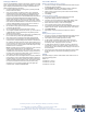
2. The PWR and GND cable from the 12 VDC power supply must be
connected to the corresponding location on the 2-pin 3.5 mm
mini-captive wire connector (FIG. 2).
3. Tighten the clamp to secure the two wires. Do not over-torque the screws;
doing so may strip the threads and damage the connector.
4. Verify the connection of the 2-pin 3.5mm mini-captive wire to the power
supply.
Connecting The NXR-ZRP-PRO To A Network
The NXR-ZRP-PRO itself has no connection to a network other than through its
ZigBee Pro gateway. To set up a ZigBee Pro gateway so it will accept a NXR-
ZRP-PRO into its ZigBee network, please refer to the NXR-ZGW-PRO/-ZRP -
PRO Operation/Reference Guide, available at www.amx.com.
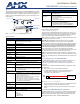
FIG. 1 The NXR-ZRP-PRO Device (front and rear)
NXR-ZRP-PRO (FG5791-03) Specifications
Dimensions (HWD): 1.00” x 2.50” x 3.50”
(23.01 mm x 64.00 mm x 87.00 mm)
Note: depth does not include antenna
Weight: 0.25 lbs (113.39g)
Power: • 10.5 - 18 VDC; (13.5 VDC nominal operation voltage)
Memory: • 1 Megabit external memory
Radio Specifications:
Frequency
2.4GHz
Operating channels
11 - 26
Modulation
technique
DSS
Output power
Region/country specific
Coverage area 165 feet (50.2m) in a typical multiwall structure
Firmware/Software Specifications:
Management Built-in browser-based management with User Name/
Password authentication (through an NXR-ZGW-PRO only)
IP configuration Static IP or DHCP client through an NXR-ZGW-PRO (default
is DHCP/Zeroconf)
Communications • ZigBee Pro 2007
• The NXR-ZRP-PRO communicates with a NetLinx Master
via an NXR-ZGW-PRO.
Front Components:
LEDs • PWR/STATUS - Green LED blinks to indicate the device is
powered but not commissioned to a network. A solid light
indicates a device powered up and commissioned; Power
OFF is indicated with no light.
• ICSP - The LED is solid when the device is connected to
the gateway and off when not connected.
• RF - The LED is solid when end devices are connected;
end devices not connected is indicated with no LED light;
the LED blinks to indicate activity.
Antenna Mount A reverse SMA connection that supports a 2.4GHz antenna.
ID Button Press and hold for approximately 10 seconds to return the
NXR-ZRP-PRO to factory default settings.
Rear Components:
Power connector • 2-pin 3.5mm captive-wire connector
Certifications: • FCC ID: CWU-NXR-ZGW
• IC: 5078A-NXRZGW
•CE
• IEC-60950
• Japan Approval
• ZigBee Certified
PWR
12VDC
RESETANT
RF
ICSP
PWR/STATUS
(Front)
(Rear)
Reset Button
Antenna Mount
2-pin 3.5mm
Connection LEDs
power connector
captive-wire
NXR-ZRP-PRO Specifications (Cont.)
Operating/Storage
Environments:
• Operating Temperature: -30°C (-22°F) to 70°C (158°F)
• Relative Humidity: 5% to 85% non-condensing; intended
for indoor use only
Included
Accessories:
• Rubber feet
• Velcro mounting strip
• 2.4GHZ, MONO, RSMA, 3.5IN, 2.0DBI Antenna
(70-0012-SA)
• Power Supply (24-5791-SA)
Other AMX Products: • Mio Modero R-3 Remote (FG148-03)
• Mio Modero R-4 Remote (FG148-04)
• NXR-ZGW-PRO ZigBee Pro Gateway (FG5791-11)
• NXA-WAP 2413A Mounting Bracket (FG2255-24)
FIG. 2
12 VDC Power Connector Wiring Diagram
To the Device
PWR +
GND -
12 VDC
Power Supply