
User Manual

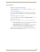


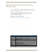
Table Of Contents
- NXR-ZGW/-ZRPNetLinx ZigBee Compatible Gatewayand Repeater
- Overview
- Installation
- Setting up a Network
- NXR-ZGW Browser-based Configuration Manager Pages
- Summary of Gateway Settings
- Configuration
- Personal Area Network (PAN)
- Network
- Enabling and disabling the wireless network
- Setting the PAN channel
- Security
- Access List
- Connections
- Finding a device’s EUI address
- Finding the device’s description
- Determining the device type
- Finding the amount of time a signal takes from the device to the gateway and back
- Determining the device link quality
- Checking the device link status
- PAN Device Details
- Putting a device on the Access List
- Removing a device from the Access List
- Locating the device
- Changing a Connected Device description
- Changing a device’s ZigBee networking information
- Utilities
- Device Configuration

Installation
10
NXR-ZGW/-ZRP
Connecting the NXR-ZGW to a LAN
Insert one end of the CAT5 Ethernet cable into the rear RJ-45 jack (illustrated in FIG. 1) and connect the
other end of the same cable to a master. See Mesh Network Arrangements section on page 6 for possible
network configurations.
Connecting Power to the NXR-ZGW and NXR-ZRP
The NXR-ZGW receives power via either PoE or 2-pin 3.5 mm mini-Phoenix connection, the
NXR-ZRP only utilizes the 2-pin 3.5 mm mini-Phoenix connection.
If PoE is selected, the NXR-ZGW will draw power through the CAT5 Ethernet cable.
If the 2-pin 3.5 mm mini-Phoenix is selected, the following steps are necessary:
Preparing captive wires for the 2-pin 3.5 mm mini-Phoenix connector
You will need a wire stripper and flat-blade screwdriver to prepare and connect the captive wires.
1. Strip 0.25 inch (6.35 mm) of wire insulation off all wires.
2. Insert each wire into the appropriate opening on the connector according to the wiring diagrams and
connector types described in this section.
3. Turn the screws clockwise to secure the wires in the connector. Do not over-torque the screws;
doing so can bend the seating pins and damage the connector.
Using the PSN NetLinx connector for power
The PWR and GND cable from the 12 VDC power supply must be connected to the corresponding
location on the 2-pin 3.5 mm mini-Phoenix connector (FIG. 5).
1. Insert the PWR and GND wires on the terminal end of a PSN 2-pin 3.5 mm mini-Phoenix cable.
Match the wiring locations of the +/- on both the power supply and the terminal connector.
2. Tighten the clamp to secure the two wires. Do not over-torque the screws; doing so may strip the
threads and damage the connector.
3. Verify the connection of the 2-pin 3.5 mm mini-Phoenix to the power supply.
Table top installation of the NXR-ZGW and NXR-ZRP
Using the provided rubber pads, place one in each bottom corner of the device.
Rack mounting the NXR-ZGW and NXR-ZRP
Using the Velcro pad provided, remove the backing and adhere one side to the device. Remove the
backing of the other side of the Velcro and place it on your rack where you want the NXR-ZGW/ZRP
mounted.
Before continuing, consult Setting up a Network section on page 23.
FIG. 5 12 VDC Power Connector Wiring Diagram
PWR +
GND -
To the Device
12 VDC Power Supply