Operation/Reference Guide NXR-ZGW/-ZRP NetLinx ZigBee Compatible Gateway and Repeater Control System Accessories
AMX Limited Warranty and Disclaimer AMX warrants its products to be free of defects in material and workmanship under normal use for three (3) years from the date of purchase from AMX, with the following exceptions: • Electroluminescent and LCD Control Panels are warranted for three (3) years, except for the display and touch overlay components that are warranted for a period of one (1) year.
Software License and Warranty Agreement LICENSE GRANT. AMX grants to Licensee the non-exclusive right to use the AMX Software in the manner described in this License. The AMX Software is licensed, not sold. This license does not grant Licensee the right to create derivative works of the AMX Software. The AMX Software consists of generally available programming and development software, product documentation, sample applications, tools and utilities, and miscellaneous technical information.
Table of Contents Table of Contents Overview ............................................................................................................1 NXR-ZGW Specifications........................................................................................... 1 NXR-ZRP Specifications ............................................................................................ 3 How ZigBee works....................................................................................................
Table of Contents User Settings ................................................................................................................. 17 Setting a new username and password ......................................................................... 17 Personal Area Network (PAN)................................................................................. 18 Network ........................................................................................................................
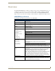
Overview Overview The NXR-ZGW (FG5791-01) is an Ethernet to ZigBee wireless gateway. The NXR-ZGW features a 10/ 100 Ethernet port capable of Power over Ethernet (PoE), 16 Mbytes of Flash, 16 Mbytes of SDRAM, and a ZigBee module, and is controlled via a web server interface. The NXR-ZRP (FG5791-02) is a ZigBee wireless repeater that features 16 Mbytes of Flash, 16 Mbytes of SDRAM, and a ZigBee module. NXR-ZGW Specifications The following table outlines the specifications for the NXR-ZGW.
Overview NXR-ZGW (FG5791-01) Specifications (Cont.) Rear Components: Power connector Two power options are available: • 2-pin 3.5mm Phoenix connector • Power Over Ethernet (PoE) - powers the device through the CAT5 cable. Both Power and Data can be transmitted simultaneous through the CAT5 cable when using the appropriate equipment.
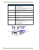
Overview NXR-ZRP Specifications The following table outlines the specifications for the NXR-ZRP. NXR-ZRP (FG5791-02) Specifications Dimensions (HWD): • 906 x 2.500 x 3.424 (23.01 mm x 63.50 mm x 86.96 mm) depth does not include antenna Weight: • 0.25 lbs (113.39g) Power: 10.5 - 18 VDC; 13.5 (nominal operation voltage) Memory: • 16 Mbytes of Flash • 16 Mbytes of SDRAM Radio Specifications: Frequency IEEE 802.15.4 Operating channels • 11 - 26 Data Rate • 250 kbps (@2.
Overview NXR-ZRP (FG5791-02) Specifications (Cont.) Other AMX Products: • Mio Modero R-3 Remote (FG148-03) • Mio Modern R-4 (FG148-04) • NXR-ZGW NetLinx ZigBee Gateway (FG5791-01) • NXA-WAP 2403A (FG2255-20) • NXA-WAP 2405A (FG2255-21) • NXA-WAP 2413A (FG2255-24) Connection LEDs Reset Button PWR/STATUS ICSP RF ANT RESET (Front) Antenna Mount 12VDC 2-pin 3.5mm Phoenix power connector PWR (Rear) FIG.
Overview How ZigBee works The NXR-ZGW, acting as a gateway, allows ZigBee-enabled devices to communicate both to and from an ICSP master. A device connects to the NXR-ZGW and is then represented to the master as an ICSP device. The master then communicates to the device through ICSP messages via a translation step at the NXR-ZGW level.
Overview Mesh Network Arrangements The following installations depend upon the criteria for the network. A home installation would perhaps only need one NXR-ZGW or PAN ID where a commercial installation might require a NXR-ZGW and several NXR-ZRPs with a unique PAN ID for each. Further, while encryption enabling is always a good idea, it might be absolute for installation with public exposure.
Overview Multiple PAN ID installations A more commercial application of the NXR-ZGW is having multiple gateways and specific devices operating in close proximity of each other. End devices and repeaters of different networks can operate side-by-side without interference if they have different PAN ID numbers. See Setting up a Network section on page 23 for setting the PAN ID and adding device EUI Addresses.
Overview 8 NXR-ZGW/-ZRP
Installation Installation Things to Consider Before Starting Several factors will help decide the best place to install NXR-ZGW and NXR-ZRP devices. Before installing, consider the following: Location and Antenna Direction The best location for NXR-ZGW and NXR-ZRP devices are usually in the center of your wireless network, with line of sight to all of your mobile devices. Try to place the antenna in a position that can best cover your wireless network.
Installation Connecting the NXR-ZGW to a LAN Insert one end of the CAT5 Ethernet cable into the rear RJ-45 jack (illustrated in FIG. 1) and connect the other end of the same cable to a master. See Mesh Network Arrangements section on page 6 for possible network configurations. Connecting Power to the NXR-ZGW and NXR-ZRP The NXR-ZGW receives power via either PoE or 2-pin 3.5 mm mini-Phoenix connection, the NXR-ZRP only utilizes the 2-pin 3.5 mm mini-Phoenix connection.
Setting up a Network Setting up a Network After you have established the location of the gateway (page 9), connected it (page 10), provided power (page 10), and placed the device in either a rack(page 10) or wall installation (page 10) you can then begin configuring the NXR-ZGW and adding an NXR-ZRP and ZigBee-compatible devices to the network. 1. Confirm the NXR-ZGW is receiving power by checking the PWR LED (See “Front and Rear Components of the NXR-ZGW” on page 2.). 2.
Setting up a Network 12 NXR-ZGW/-ZRP
NXR-ZGW Browser-based Configuration Manager Pages NXR-ZGW Browser-based Configuration Manager Pages To access the Configuration Manager pages, enter the IP address of the NXR-ZGW into your web browser; the default IP address for the NXR-ZGW is 192.168.1.140. When prompted, enter your username and password in the spaces provided. Upon accessing the Configuration Manager, the user must enter a username and password.
NXR-ZGW Browser-based Configuration Manager Pages Summary Page (Cont.) Pan ID The ZigBee personal area network ID used. Security The current state of wireless security (Disabled/Enabled). Access List The current state of the Access List (Disabled/Enabled). Distribute Password Current mode of ZigBee password distribution (Disabled/Enabled). Checking the firmware version The firmware version is listed on the Summary of Gateway Settings page of the NXR-ZGW Browserbased Configuration Manager.
NXR-ZGW Browser-based Configuration Manager Pages Configuration Network IP Settings The Network IP Settings page is used to set IP and DNS addresses. The IP address can be either a static or dynamic assignment. FIG. 7 IP Settings Page IP Address IP • Dynamic: IP address and subnet mask are requested from the DHCP server. • Static: User provides IP address information. Host The hostname of the unit. IP Address The IP address of the unit. Subnet Mask The IP subnet mask of the unit.
NXR-ZGW Browser-based Configuration Manager Pages 3. Type the Domain Suffix in the field provided. 4. Type the necessary DNS IP numbers in the fields. 5. Click Accept. 6. In the The system will need to reboot for changes to take effect window, click OK. NetLinx Settings This page specifies the ICSP connection to the NetLinx master. FIG.
NXR-ZGW Browser-based Configuration Manager Pages User Settings This page is used to set the username and password for access to the NXR-ZGW web server pages. FIG. 9 User Settings page User Settings Page New Username Text field for new username. New Password Text field for new password. Re-type Password Text field to confirm new password. Setting a new username and password 1.
NXR-ZGW Browser-based Configuration Manager Pages Personal Area Network (PAN) Network The Network page allows you to modify the status of the Personal Area Network. FIG. 10 Network Page Network Page Network status Lists whether the network is online or offline. Wireless Enables or disables the ZigBee wireless networking. PAN ID The current PAN ID number for the device. Country/Region Drop down menu; sets ZigBee region (US, Europe, Japan).
NXR-ZGW Browser-based Configuration Manager Pages Security The Security page allows and sets the method by which devices connect to the PAN. FIG. 11 Pan Security Settings Page Pan Security Settings Page Security Enables or disables the ZigBee security. AES Key This is the security key used by the ZigBee network. This field is currently greyed out. Access List The Access List catalogues all of the available devices currently running through the Personal Access Network.
NXR-ZGW Browser-based Configuration Manager Pages Connections All devices connected to the NXR-ZGW is displayed on this page. FIG. 12 Connections Page Each device provides the following: Connections Page No. The Netlinx ID number. EUI-64 The 64 bit ZigBee EUI address of the device. Description The device's description, supplied by the device. Type The specific type of device being accessed.
NXR-ZGW Browser-based Configuration Manager Pages Finding a device’s EUI address 1. In the menu on the top of the NXR-ZGW Browser-based Configuration Manager, select Connections under the section Pan. 2. The EUI address is located in the Connections table under "EUI-64". Click on the EUI address to open the PAN Device Details page for this device. (See FIG. 13) Finding the device’s description 1.
NXR-ZGW Browser-based Configuration Manager Pages PAN Device Details From both the Pan Security Settings and the Connections pages, clicking on a device’s EUI-64 number opens the PAN Device Details page. FIG. 13 PAN Device Details Page Each device provides the following: PAN Device Details Page Device Options • On Access List: Controls whether the device is on the access list for the Connections page. • Locate: Finds the location of the device if active.
NXR-ZGW Browser-based Configuration Manager Pages PAN Device Details Page (Cont.) ZigBee Networking • Application Version: The version of the ZigBee application being used. • Pan ID: ID number for the device within the PAN. • AES Key: This is the security key used by the ZigBee network. Connection Log The device or devices currently or previously connected to the network. Putting a device on the Access List 1.
NXR-ZGW Browser-based Configuration Manager Pages 2. Click the Accept button. A new window opens that reads "Are you sure you wish to accept these new changes?" Click OK to accept the new changes. 3. If the device is active, the PAN Device Details page will refresh, displaying the completed changes.
NXR-ZGW Browser-based Configuration Manager Pages Utilities Device Firmware The device details page shows all the information about the status of firmware on a network’s devices. FIG. 14 Device Firmware Page Device Firmware Updates Permissions to allow firmware uploads to the selected device. EUI-64 The 64-bit EUI address of the device. Description The name and location of the device, as provided by the device. Status The current activity of the device, whether active or asleep.
NXR-ZGW Browser-based Configuration Manager Pages 2. Choose the device to be updated by its EUI-64 number. 3. Click the button next to the device’s EUI-64 number in the Allow Updates column. The page will automatically refresh, displaying the device’s new status. 4. Some devices cannot have their firmware update status changed; these devices will continue to read Off even after selecting to allow new updates. Allowing firmware updates to all devices on a network 1.
NXR-ZGW Browser-based Configuration Manager Pages Determining the connection status of a device 1. In the menu on the top of the NXR-ZGW Browser-based Configuration Manager, select Connection Log under the section Utilities. 2. The connection status of each device is located in the column Connection; the possible values are either Connected or Disconnected. Finding a device’s EUI address 1.
NXR-ZGW Browser-based Configuration Manager Pages Traffic Log The traffic log shows traffic statistics for all ZigBee devices. FIG. 16 Traffic Log Page Traffic Log Page Device # The device's ICSP device number. EUI-64 The 64-bit EUI address of the device. Description The device's description, supplied by the device. Device Type The types are: • End Device • Repeater • PAN coordinator. RX The total number of bytes received by the device since it connected.
NXR-ZGW Browser-based Configuration Manager Pages 1. In the menu on the top of the NXR-ZGW Browser-based Configuration Manager, select Traffic Log under the section Utilities. 2. The description of each device is located in the column Description. Determining the device type 1. In the menu on the top of the NXR-ZGW Browser-based Configuration Manager, select Traffic Log under the section Utilities. 2. The type of each device is located in the column Device Type. Finding the device traffic 1.
NXR-ZGW Browser-based Configuration Manager Pages 30 NXR-ZGW/-ZRP
Device Configuration Device Configuration Sending Firmware to The NXR-ZGW Before beginning the Upgrade process Set up and configure your NetLinx Master. Refer to your particular NetLinx Master instruction manual for detailed setup procedures. Prepare the communication on the NXR-ZGW for use. Refer to the Setting up a Network section on page 11. Refer to the NetLinx Studio version 2.4 or higher Help file for information on uploading firmware files via Ethernet.
Device Configuration Upgrading The NXR-ZGW via An IP Address Before beginning this section, verify that your device is powered and connected to the NetLinx Master through an Ethernet connection. Preparing the Master for communication via an IP 1. Obtain the IP Address of the NetLinx Master from your System Administrator. If you do not have an IP Address for the Master, refer to your particular Master’s instruction manual for more information on obtaining an IP Address using NetLinx Studio 2.4 or higher.
Device Configuration 12. Select Tools > Reboot the Master Controller to access the Reboot the Master dialog, then click Reboot to reboot the Master and incorporate any changes. 13. Once the dialog replies with "Reboot of system complete", press Done. 14. Click the OnLine Tree tab in the Workspace window to view the devices on the System. The default System value is one. 15. Right-click on the Empty Device Tree/System entry and select Refresh System to re-populate the list.
Device Configuration 8. Click the Reboot Device checkbox. This causes the NXR-ZGW device to reboot after the firmware update process is complete. 9. Click Send to begin the transfer. The file transfer progress is indicated on the bottom-right of the dialog (FIG. 18). Do not pull power from device during transfer, it can take approximately 5 minutes to finalize firmware transfer. The upgrade can still be in progress when the bargraph reaches the end, it is a good idea to wait until the process is complete.
Device Configuration NXR-ZGW/-ZRP 35
3/07 ©2006 AMX. All rights reserved. AMX and the AMX logo are registered trademarks of AMX. AMX reserves the right to alter specifications without notice at any time. It’s Your World - Take Control™ 3000 RESEARCH DRIVE, RICHARDSON, TX 75082 USA • 800.222.0193 • 469.624.8000 • 469-624-7153 fax • 800.932.6993 technical support • www.amx.