NX-Series NetLinx Integrated Controllers Hardware Reference Guide Hardware Reference Manual NX-Series NetLinx Integrated Controllers NX-1200, NX-2200 NX-3200, NX-4200 Central Controllers Latest Release: 8/8/2014
AMX DOMESTIC CHANNEL PARTNER and END CUSTOMER LIMITED WARRANTY, DISCLAIMER AND LICENSE (Excerpt from CHANNEL PARTNER TERMS AND CONDITIONS Versions 11.17.2011 with updates for previous version 8.25.2010 [sections 6.1 (a), (b) and (f)]) Definitions “End Customer” means an authorized end customer with direct in warranty privileges from AMX. Within this limited warranty, disclaimer and license document, “End Customer” shall have the same meaning as “Channel Partner” with the noted exceptions of Sections 6.
Notices Copyright Notice AMX© 2013, all rights reserved. No part of this publication may be reproduced, stored in a retrieval system, or transmitted, in any form or by any means, electronic, mechanical, photocopying, recording, or otherwise, without the prior written permission of AMX.
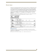
US FCC Notice (Class A) The United States Federal Communications Commission has specified that the following notice be brought to the attention of the users of this product. Federal Communication Commission Radio Frequency Interference Statement: “This equipment has been tested and found to comply with the limits for a Class A digital device, pursuant to Part 15 of the FCC Rules.
Table of Contents Table of Contents Overview ............................................................................................................1 Related Documents ......................................................................................................... 1 What’s New?............................................................................................................. 2 Two Discrete Network Interfaces (NICs)....................................................................
Table of Contents Mounting the Controller ......................................................................................... 17 Installing the Controller into an Equipment Rack .......................................................... 17 Rack Mount Safety Instructions ..................................................................................... 17 Mounting the NX-1200 .................................................................................................
Table of Contents LAN 10/100 Port ........................................................................................................... 32 IPv4 ........................................................................................................................................... 32 IPv6 ........................................................................................................................................... 32 INPUT PWR Connector .................................................
Overview Overview The NX-series of NetLinx Integrated Master Controllers can be programmed to control Ethernet, RS-232/422/ 485, Relay, IR, and Input/Output devices, as well as other AMX devices connected via AxLink, through the use of both NetLinx and Java programming languages. NetLinx programs are developed using the NetLinx Studio application version 4.x. Java programs are developed using the Cafe Duet application.
Overview What’s New? The following section lists the new features for the NX-series controllers. For more information about each of these items, see the What’s New for NX-Series Controllers document located on the NX controllers product pages at www.amx.com. Two Discrete Network Interfaces (NICs) The NX-2200, NX-3200 and NX-4200 controllers have two 10/100BaseT Ethernet connections.
Overview Case Sensitive File System Unlike the NI-Series controllers, all file names on the X-Series controllers are case sensitive. This includes all user files created or used within NetLinx or Java code. USB Program Port The X-Series controllers utilize a true USB port for configuration and programming via a connected PC. USB Firmware Upgrade All X-Series controllers support firmware upgrades via a USB solid-state drive. Selecting the desired .kit file and initiating the upgrade are done from telnet.
Overview Features The following table summarizes the features for each NX-series controller: NX-Series Controllers - Features NX-1200 NetLinx Integrated Controllers Name / FG# Features NX-1200 Controller (FG2106-01) 1 RS-232 / RS-422 / RS-485 serial port 1 RS-232-only serial port 2 IR / Serial ports 4 Digital I/O ports 1 AxLink port 1 LAN Ethernet port 1 IR Receiver port capable of interfacing with an AMX IR03 1 USB 2.
Overview NX-Series Controllers - Features (Cont.) NX-4200 NetLinx Integrated Controllers Name / FG# Features NX-4200 Controller (FG2106-04) 2 RS-232 / RS-422 / RS-485 serial ports 6 RS-232-only serial port 8 Relays 8 IR / Serial ports 8 Digital I/O ports 2 AxLink ports 4 ICSNet Ethernet ports 1 LAN Ethernet port 2 USB 2.
Overview NX-1200 Specifications NX-1200 Specifications Dimensions (HWD): 1.645" x 5.8" x 5.15" (41.78mm x 147.32mm x 130.81mm) RU: 1/3 Active Power Requirements: • DC input voltage (typical): 12 VDC • DC current draw: 200 mA @ 12 VDC • DC range, voltage: 9-18 VDC Active Power Consumption: 3W Memory: • 512 MB DDRAM • 1 MB Non-volatile RAM (NVRAM) • 4 GB Internal MicroSD memory card Weight: 1.6 lbs (0.
Overview NX-1200 Specifications (Cont.) Rear Panel Components: Digital I/O (Port 22): 1 6-pin 4-channel binary I/O port for contact closure with each input being capable of voltage sensing. Input format is software selectable with interactive power sensing for IR ports. IR/Serial (Ports 11-12): 2 2-pin IR/Serial control ports support high-frequency carriers of up to 1.142 MHz with each output being capable of two electrical formats: IR or Serial. 2 IR/Serial data signals can be generated simultaneously.
Overview NX-2200 The NX-2200 (FG2106-02) has 512MB of on-board RAM, a 4GB CompactFlash card, and is Device Discovery enabled to simplify programming by standardizing device and function definitions, default touch panel button assignments, and control and feedback methods. A complete list of device specifications is listed below. FIG. 3 displays the NX-2200. FIG. 3 NX-2200 (front and rear panels) Note: Verify you are using the latest NX firmware for the on-board Master.
Overview NX-2200 Specifications (Cont.) USB Port: 1 Type-A USB port for connecting a mass storage device for loading .tkn files, reading or writing configuration files and log files, or updating the firmware on the unit. Master LEDs: • LINK/ACT (green): Blinks when the Ethernet cables are connected and terminated correctly. Also blinks when receiving Ethernet data packets. • STATUS (green): Blinks to indicate that the system is programmed and communicating properly.
Overview NX-2200 Specifications (Cont.) LAN 10/100 Port: 1 RJ-45 connector provides TCP/IP communication. This is an Auto MDI/MDI-X enabled port, which allows you to use either straight-through or crossover Ethernet cables. The Ethernet Port LEDs show communication activity, connection status, speeds, and mode information: • SPD (speed) - Yellow LED lights On when the connection speed is 100 Mbps and turns Off when the speed is 10 Mbps.
Overview NX-3200 The NX-3200 (FG2106-03) has 512MB of on-board RAM, a 4GB CompactFlash card, and is Device Discovery enabled to simplify programming by standardizing device and function definitions, default touch panel button assignments, and control and feedback methods. A complete list of device specifications is listed below. FIG. 4 displays the NX-3200. FIG. 4 NX-3200 (front and rear panels) Note: Verify you are using the latest NX firmware for the on-board Master.
Overview NX-3200 Specifications (Cont.) USB Port: 1 Type-A USB port for connecting a mass storage device for loading .tkn files, reading or writing configuration files and log files, or updating the firmware on the unit. Master LEDs: • LINK/ACT (green): Blinks when the Ethernet cables are connected and terminated correctly. Also blinks when receiving Ethernet data packets. • STATUS (green): Blinks to indicate that the system is programmed and communicating properly.
Overview NX-3200 Specifications (Cont.) LAN 10/100 Port: RJ-45 connector provides TCP/IP communication. This is an Auto MDI/MDI-X enabled port, which allows you to use either straight-through or crossover Ethernet cables. The Ethernet Port LEDs show communication activity, connection status, speeds, and mode information: • SPD (speed) - Yellow LED lights On when the connection speed is 100 Mbps and turns Off when the speed is 10 Mbps.
Overview NX-4200 The NX-4200 (FG2106-04) has 1GB of on-board RAM, a 13GB CompactFlash card, and is Device Discovery enabled to simplify programming by standardizing device and function definitions, default touch panel button assignments, and control and feedback methods. A complete list of device specifications is listed below. FIG. 5 displays the NX-4200. FIG. 5 NX-4200 (front and rear panels) The NX-4200’s on-board Master also provides the ability to update installed control card firmware.
Overview NX-4200 Specifications (Cont.) Program Port 1 Type-B USB port that can connect to a USB port on a PC and access the NetLinx Studio program for controller configuration. USB Port 1 Type-A USB port for connecting a mass storage device for loading .tkn files, reading or writing configuration files and log files, or updating the firmware on the unit. Display Control Button 1 rocker-style tactile button for stepping through the supported status parameters displayed on the front panel LCD.
Overview NX-4200 Specifications (Cont.) ICSLAN Ports: 4 RJ-45 connectors for ICSLAN interface with support for PoE. USB Port: 1 Type-A USB port for connecting a mass storage device for loading .tkn files, reading or writing configuration files and log files, or updating the firmware on the unit. ID Pushbutton: 1 black ID pushbutton used during boot to revert to factory configuration or factory firmware. Also used after boot to toggle IP mode between Static and DHCP.
Overview Mounting the Controller Use the rack-mounting brackets (supplied with the NX-2200/3200/4200) for equipment rack installations. Remove the mounting brackets and apply the rubber feet to the bottom of the controller for flat surface installations. Installing the Controller into an Equipment Rack The NX-2200/3200/4200 each ship with removable rack ears for installation into an equipment rack. The following instructions apply to the NX-2200/3200/4200.
Overview 5. Secure the controller to the rack by using the four #10-32 screws supplied in the kit. 6. Apply power to the unit to complete the installation.
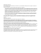
Wiring and Connections Wiring and Connections Overview This chapter provides details, specifications, wiring diagrams, and other important information for all port and connectors available on the NX-series controllers. FIG. 1 displays the NX-series controllers. FIG. 1 NX-series controllers Front Panel Components The following sections list the front panel components on the NX-series controllers. Each component is featured on all NX-series controllers except where noted.
Wiring and Connections USB Port The front panel of all models features one Type-A USB port you can use to connect a mass storage device for loading .tkn files, reading or writing configuration files and log files, or updating the firmware on the unit. Note: This USB port only supports a FAT32 file system. This USB port (FIG. 4) uses standard USB cabling to connect to any mass storage or peripheral devices. FIG. 4 USB port Note: USB hubs are not supported on this port.
Wiring and Connections PoE General Status Format The PoE General Status front panel display item contains the following status definitions: PoE Not Available - The system is not being powered from an AC source. OK: xx.xW - No general faults are present, where xx.x is the total power in watts currently being provided on the PoE ports. Max Power Exceeded - The total power drawn on the ports is greater than the PoE power capacity. Voltage Fault - The PoE voltage is out of range.
Wiring and Connections The following table lists the following special LED patterns for the Status, Input, and Output LEDs: LED Patterns Mode Description Status Output Input OS Start Starting the Operating System ON ON ON Boot On-board Master is booting ON OFF ON Contacting DHCP server On-board Master is contacting a DHCP server for IP configuration information ON OFF Fast Blink Using link-local address On-board Master could not find a DHCP server and is using a link-local address Slo
Wiring and Connections IR/SERIAL LEDs The IR/SERIAL LEDs light red to indicate that the corresponding IR/Serial port is transmitting data. There are eight IR/SERIAL LEDs on the NX-3200 and NX-4200. The NX-2200 has four IR/SERIAL LEDs. The NX-1200 has two IR LEDs (see FIG. 9). NX-3200/4200 FIG. 10 IR/SERIAL LEDs NX-2200 NX-1200 I/O LEDs The I/O LEDs light yellow to indicate that the corresponding I/O port is active. There are eight I/O LEDs on the NX-3200 and NX-4200.
Wiring and Connections Rear Panel Components The following sections list the rear panel components on the NX-series controllers. FIG. 14 displays the rear panels of the NX-series controllers. FIG. 14 NX-series controllers (rear panels) Serial Ports The NX-series controllers each feature device control serial ports that support either RS-232 or RS-232, RS-422, and RS-485 communication protocols.
Wiring and Connections RS-232/422/485 Ports The RS-232/422/485 ports (ports 1 and 5 on the NX-3200/4200; port 1 on the NX-1200/2200) are 10-pin 3.5 mm mini-Phoenix (male) connectors used for connecting A/V sources and displays. By default, these ports are RS-422- and RS-485-disabled ports. These ports can be used as RS-232 ports by disabling RS-422 and RS-485 on the ports. Only with RS-422/485 disabled will the ports operate as RS-232.
Wiring and Connections Relay Ports The relay ports (port 21 on the NX-2200/3200/4200) are 8-pin 3.5 mm mini-Phoenix (male) connectors used for connecting external relay devices. The NX-3200 and NX-4200 each features 2 sets of 8-pin relay connectors. The NX-2200 features one set of connectors. You can connect up to 8 independent external relay devices on both the NX-3200 and NX-4200 units, and 4 on the NX-2200. When a relay is "OFF", terminals A and B are open-circuit.
Wiring and Connections I/O Port Wiring Specifications NX-3200/4200 NX-1200/2200 Pin Signal Function Pin Signal Function 1 GND Signal GND 1 GND Signal GND 2 I/O 1 Input/Output 2 I/O 1 Input/Output 3 I/O 2 Input/Output 3 I/O 2 Input/Output 4 I/O 3 Input/Output 4 I/O 3 Input/Output 5 I/O 4 Input/Output 5 I/O 4 Input/Output 6 12 VDC PWR 6 12 VDC PWR 7 GND Signal GND 8 I/O 5 Input/Output 9 I/O 6 Input/Output 10 I/O 7 Input/Output 11 I/O 8 Input/Output 1
Wiring and Connections The IR/Serial connector wiring specifications are listed in the following table. IR/SERIAL Connector Wiring Specifications (per Port) NX-3200/ NX-2200 4200 Port # Port # NX-1200 Port # 11 11 11 12 12 12 13 13 N/A 14 14 N/A 15 N/A N/A 16 N/A N/A 17 N/A N/A 18 N/A N/A AxLink Port and LED (4-pin captive-wire) The AxLink port allows the central controller to support AMX AxLink devices. FIG. 20 displays the AXLINK ports for each NX-series controller.
Wiring and Connections FIG. 21 provides wiring requirements for the AxLink connector: To the Controller’s AxLink/PWR connector To the external AxLink device Top view Top view FIG. 21 Mini-Phoenix connector wiring diagram (direct data and power) To use the 4-pin 3.5 mm mini-Phoenix (male) captive-wire connector for data communication and power transfer, the incoming PWR and GND cable from the 12 VDC-compliant power supply must be connected to the AxLink cable connector going to the central controller.
Wiring and Connections Configuration DIP Switch The NX-series controllers each have a configuration DIP switch which allows for certain operations to occur during boot-time. The DIP switch positions are assigned as follows: Switch for Program Run Disable Switch for Boot from External SD Card (only applicable to the NX-3200 and NX-4200.) Note: The Configuration DIP Switch is located on the front panel of the NX-1200 and not the rear panel. FIG.
Wiring and Connections Using the ICSLAN Network The default IP address for the ICSLAN network is 198.18.0.1 with a subnet mask of 255.255.0.0. It is important that the ICSLAN and LAN subnets do not overlap. If the LAN port is configured such that its address space overlaps with the ICSLAN network, the ICSLAN network will be DISABLED. DHCP Server The ICSLAN port has a built-in DHCP server. This DHCP server is enabled by default and will serve IP addresses to any connected devices set to DHCP mode.
Wiring and Connections LAN 10/100 Port All NX-series controllers feature a LAN 10/100 port to provide 10/100 Mbps communication via Category cable. This is an Auto MDI/MDI-X enabled port, which allows you to use either straight-through or crossover Ethernet cables. The port support IPv4 and IPv6 networks, as well as HTTP, HTTPS, Telnet, and FTP. The LAN port automatically negotiates the connection speed (10 Mbps or 100 Mbps), and whether to use half duplex or full duplex mode. FIG.
Wiring and Connections INPUT PWR Connector All NX-series controllers feature a 2-pin 3.5 mm Phoenix connector with screw retention for providing DC power to the controller. The suggested power supply for the NX-series controllers is a 13.5 VDC 6.6 A output, suitable for 50° C. An AC power connector is also available for the NX-4200. A 100-240VAC, 60/63Hz, 3.3A power source is required to supply AC power to the controller.
Wiring and Connections Hardware Reference Guide - NX-Series NetLinx Integrated Controllers 34
In the ever-changing AV industry, continual education is key to success. AMX University is dedicated to ensuring that you have the opportunity to gather the information and experience you need to deliver strong AMX solutions. Plus, AMX courses also help you earn CEDIA, NSCA, InfoComm, and AMX continuing education units (CEUs).