
Operating instructions
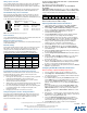
Table Of Contents
Quick Start Guide
NI-4100 NetLinx Integrated Controller
For more detailed installation, configuration, programming, file transfer, and
operating instructions, refer to the NetLinx Integrated Controllers (NI-2100,
NI-3100, and NI-4100 Series) Instruction Manual, available online at
www.amx.com.
Overview
The NI-4100 unit (FG2105-06) is geared toward those advanced control and
automation requirements associated with most complex commercial and
residential installations. The NI-4100 provides support for up to 4 NetLinx
control cards (such as NXC-COM2, NXC-IRS4, etc.),
7 RS-232/RS-422/RS-485 Ports, 8 IR/Serial Output ports,
8 Digital Input/Output ports, and 8 Relays. The NI-4100’s on-board Master
also provides the ability to update installed control card firmware.
ATTENTION!
Verify you are using the latest NI firmware for the on-board Master. Verify
you are using the latest version of NetLinx Studio (available for download
from www.amx.com).
Specifications
Connections and Wiring
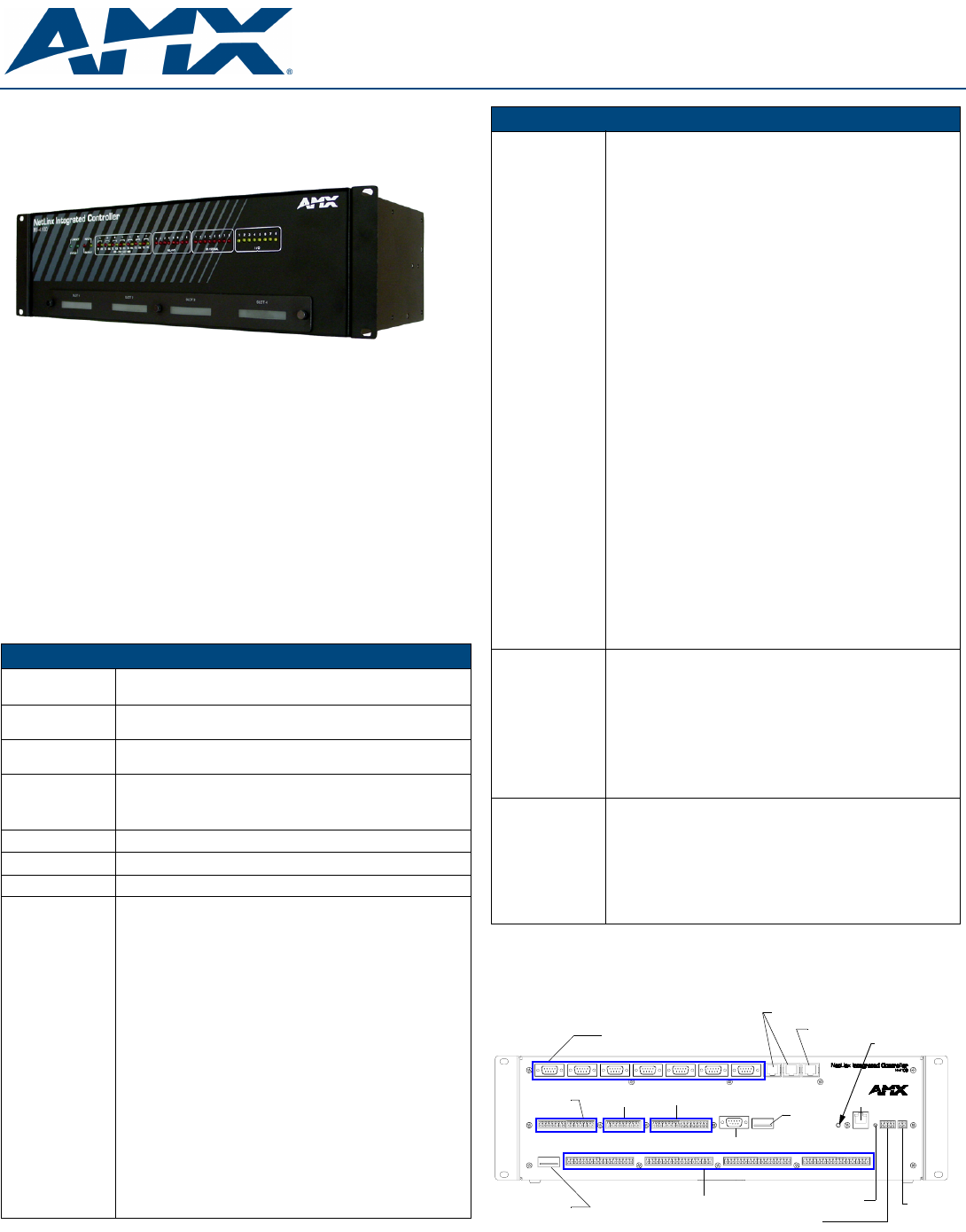
FIG. 2 shows the layout of the connectors and components located on the
rear of the NI-4100 NetLinx Integrated Controller.
FIG. 1 NI-4100 NetLinx Integrated Controller (front view)
NI-4100 Specifications
Dimensions
(HWD):
• 5.21" x 17.00" x 9.60" (13.23 cm x 43.18 cm x 24.27 cm)
• 3 rack units high
Power
Requirement:
• 900 mA @ 12 VDC
Memory: • 64 MB SDRAM
• 1 MB Non-volatile (NV) SRAM
Compact Flash: • 128 MB Card (upgradeable) (refer to the Other AMX Equipment
section for more information)
• Refer to the NetLinx Integrated Controllers (NI-2100, NI-3100,
and NI-4100 Series) Instruction Manual for more information.
Weight: • 9.15 lbs (4.15 kg)
Enclosure: • Metal with black matte finish
Certifications: • FCC Part 15 Class B, CE, and IEC 60950
Front Panel
Components:
• LINK/ACT: Green LED blinks when the Ethernet cables are
connected and terminated correctly. Also blinks when receiving
Ethernet data packets.
• Status: Green LED blinks to indicate that the system is
programmed and communicating properly.
• Output: Red LED blinks when the Controller transmits data, sets
channels On and Off, sends data strings, etc.
• Input: Yellow LED blinks when the Controller receives data from
button pushes, strings, commands, channel levels, etc.
• RS-232/422/485 LEDs: Seven sets of red and yellow LEDs light to
indicate the rear DB9 Ports 1 - 7 are transmitting or receiving
RS-232, 422, or 485 data
• Relay LEDs: Eight red LEDs light to indicate the rear relay
channels 1 - 8 are active (closed). These LEDs reflect the state of
the relay on Port 8.
• IR/Serial LEDs: Eight red LEDs light to indicate the rear IR/Serial
channels 1 - 8 are transmitting control data on Ports 9 - 16. LED
indictor for each IR port remains lit for the length of time that
IR/Serial data is being generated.
• I/O LEDs: Eight yellow LEDs light when the rear I/O channels 1 - 8
are active. LED indicator for each I/O port reflects the state of that
particular port.
• NetLinx Control Card Slot 1 - 4: Accepts up to 4 compatible
NetLinx Cards: such as the NXC-COM2, NXC-I/O10, etc.
• Rack-mount brackets: Provides an installation option for the
Integrated Controller to be mounted into an equipment rack,
when used with the Installation Kit (KA2105-01).
NI-4100 Specifications (Cont.)
Rear Panel
Connectors:
• RS-232/422/485 (Ports 1 - 7): Seven RS-232/422/485 control
ports using DB9 (male) connectors with XON/XOFF (transmit on/
transmit off), CTS/RTS (clear to send/ready to send), and
300-115,200 baud.
• ICSNet: Two RJ-45 connectors for ICSNet interface (included).
• ICSHub Out: RJ-45 connector provides data to a Hub connected
to the Controller (included).
•Relay (Port 8): 8-channel single-pole single throw relay ports with
each relay being independently controlled and supporting up to
8 independent external relay devices.
• Digital I/O (Port 17): 8-channel binary I/O port for contact closure
with each input being capable of voltage sensing. Input format is
software selectable with interactive power sensing for IR ports.
•IR/Serial (Ports 9 - 16): Eight IR/Serial control ports support
high-frequency carriers of up to 1.142 MHz with each output
being capable of two electrical formats: IR or Serial. Eight IR/
Serial data signals can be generated simultaneously. IR ports
support data mode (at limited baud rates and wiring distances).
• Program Port: RS-232 DB9 connector (male) can be connected to
a DB9 port on a PC. This connector can be used with serial and
NetLinx programming commands, as well as other DB9 capable
devices, to both upload/download information from the NetLinx
Studio program.
• Configuration DIP Switch: Sets the communication parameters for
the Program port.
• ID Pushbutton: Sets the NetLinx ID (Device only) assignment for
the device.
• Ethernet Port: LEDs show communication activity, connection
status, speeds, and mode information:
SPD (speed) - Yellow LED lights On when the connection speed
is 100 Mbps and turns Off when the speed is 10 Mbps.
L/A (link/activity) - Green LED lights On when the Ethernet cables
are connected and terminated correctly, and blinks when
receiving Ethernet data packets.
• AXlink LED: Green LED indicates the state of the AXlink port.
• AXlink Port: 4-pin 3.5 mm mini-Phoenix (male) connector that
provides data and power to external control devices.
• Power Port: 2-pin 3.5 mm mini-Phoenix (male) connector.
• CardFrame Number DIP Switch: Sets the starting address for the
Control Cards in the CardFrame. (Factory default CardFrame
DIP switch value = 0). The Control Card address range is 1-3064.
• Control Card Connectors (1 - 4): 20-pin (male) connectors that
connect the Control Cards and external equipment to the
CardFrame.
Included
Accessories:
• 2-pin 3.5 mm mini-Phoenix (female) PWR connector (41-5025)
• 4-pin 3.5 mm mini-Phoenix (female) AXlink connector (41-5047)
• 10-pin 3.5 mm mini-Phoenix (female) I/O connector (41-5107)
• Installation Kit (KA2105-01):
8-pin Relay Common Strip
Four rack mount screws
Four washers
• Quick Start Guide
• Two 8-pin 3.5 mm mini-Phoenix (female) Relay connectors
(41-5083)
• Two CC-NIRC IR Emitters
• Two removable rack ears (62-2105-07)
Other AMX
Equipment:
• 2-pin 3.5 mm mini-Phoenix male connector (41-5026)
• CSB Cable Support Bracket (FG517)
• CC-NIRC IR cables (FG10-000-11)
• CC-NSER IR/Serial cables (FG10-007-10)
• NCK, NetLinx Connector Kit (FG2902)
• STS, Serial To Screw Terminal (FG959)
• Upgrade Compact Flash (factory programmed with firmware):
NXA-CF2NI256M - 256 MB compact flash card (FG2116-47)
NXA-CF2NI512M - 512 MB compact flash card (FG2116-48)
NXA-CF2NI1G - 1 GB compact flash card (FG2116-49)
FIG. 2 NI-4100 rear connectors and components
AXlink LED
Relays
RS-232/422/485 (Ports 1-7)
I/O (Port 17)
IR/Serial (Ports 9-16)
Rear
Program port
DIP
switch
ICSNet (2)
ICSHub Out
(green)
ID Pushbutton
(Port 8)
Ethernet
AXlink port
PWR
CardFrame DIP
switch
Slot 1-4 connectors