
User's Manual


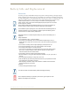
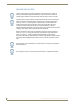
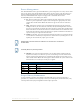


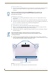
Table Of Contents
- MVP-9000i 9" Modero® ViewPoint® Touch Panel with Intercom
- Introduction
- Accessories
- Configuring Communication
- Overview
- IR Communication
- Modero Setup and System Settings
- Wireless Settings - Wireless Access Overview
- Configuring Wireless Network Access
- Step 1: Configure the Device’s WiFi Settings
- Step 2: Configure the Card’s Wireless Security Settings
- Step 3: Choose a Master Connection Mode
- Ethernet Over USB
- Using G4 Web Control to Interact with a G4 Panel
- Using the NetLinx Master To Control the G4 Panel
- Setup Pages
- Protected Setup Pages
- Upgrading Firmware
- Programming
- Overview
- Animated Transitions
- Touch Gesture Recognition
- Page Commands
- Programming Numbers
- "^" Button Commands
- Text Effects Names
- Button Query Commands
- Panel Runtime Operations
- Input Commands
- Embedded codes
- Panel Setup Commands
- Dynamic Image Commands
- Intercom Commands
- SIP Commands
- ^PHN- AUTOANSWER
- ^PHN-CALL
- ^PHN-DECLINE
- ^PHN-INCOMING
- ^PHN- LINESTATE
- ^PHN- MSGWAITING
- ^PHN-PRIVACY
- ^PHN-REDIAL
- ^PHN- TRANSFERRED
- ^PHN-ANSWER
- ^PHN- AUTOANSWER
- ?PHN- AUTOANSWER
- ^PHN-CALL
- ^PHN-DTMF
- ^PHN-HANGUP
- ^PHN-HOLD
- ?PHN- LINESTATE
- ^PHN-PRIVACY
- ?PHN-PRIVACY
- ^PHN-REDIAL
- ^PHN- TRANSFER
- ^PHN-SETUP- DOMAIN
- ^PHN-SETUP- ENABLE
- ^PHN-SETUP- PASSWORD
- ^PHN-SETUP- PORT
- ^PHN-SETUP- PROXYADDR
- ^PHN-SETUP- STUNADDR
- ^PHN-SETUP- USERNAME
- Battery Life and Replacement
- Appendix A: Text Formatting
- Appendix B: Wireless Technology
- Appendix C: Troubleshooting
- Overview
- Panel Doesn’t Respond To Touches
- Battery Will Not Hold Or Take A Charge
- MVP-9000i Isn’t Appearing In The Online Tree Tab
- MVP Can’t Obtain a DHCP Address
- My AP Doesn’t Seem To Be Working
- NetLinx Studio Only Detects One Of My Connected Masters
- Can’t Connect To a NetLinx Master
- Only One Modero Panel In My System Shows Up
- Panel Behaves Strangely After Downloading A Panel File Or Firmware
- Overview

Battery Life and Replacement
187
MVP-9000i Modero® Wireless Touch Panel with Intercom
4. Remove the two screws underneath the IR emitter cover (FIG. 113).
5. Remove the five screws from the back of the device (FIG. 114).
Two of the screws are at the upper corners of the device, underneath rubber feet that also act as
screw covers. Remove the rubber feet to access the screws.
Lift up the kickstand and remove the label to reach the remaining three screws.
6. Discharge all static electricity that may have built up on your body, either by using a static discharge strap
or by touching a nearby piece of metal.
7. Carefully remove the back of the device and detach the battery lead at the battery connector (FIG. 115).
This will allow the back cover to be detached from the device.
FIG. 113 Placement of screws underneath IR emitter cover
FIG. 114 Placement of screws on the back of the MVP-9000i
FIG. 115 Interior of MVP-9000i, including female battery connector
Screws under IR emitter cover
Two screws under upper screw covers
3 screws under label
(beneath kickstand)
Battery (shown on
Battery connector
Battery lead
device for clarity)