Installation Guide MVP-WDS Wall Docking Station for MVP-7500/8400 Modero® ViewPoint® Wireless Touch Panels Touch Panels & Accessories Last Revised: 12/15/2008
AMX Limited Warranty and Disclaimer AMX warrants its products to be free of defects in material and workmanship under normal use for three (3) years from the date of purchase from AMX, with the following exceptions: • Electroluminescent and LCD Control Panels are warranted for three (3) years, except for the display and touch overlay components that are warranted for a period of one (1) year.
FCC Information This device complies with Part 15 of the FCC Rules. Operation is subject to the following two conditions: (1) this device may not cause harmful interference, and (2) this device must accept any interference received; including interference that may cause undesired operation. Federal Communications Commission (FCC) Statement This equipment has been tested and found to comply with the limits for a Class B digital device, pursuant to Part 15 of the FCC rules.
Table of Contents Table of Contents MVP-WDS Wall Docking Station & CB-MVPWDS Rough-In Box .........................1 Overview .................................................................................................................. 1 Specifications ................................................................................................................. 2 MVP-WDS docking station connector locations .............................................................. 3 LED Indicators .............
Table of Contents ii MVP-WDS Wall Docking Station for MVP Panels
MVP-WDS Wall Docking Station & CB-MVPWDS Rough-In Box MVP-WDS Wall Docking Station & CB-MVPWDS Rough-In Box Overview The MVP-WDS Wall/Flush Mount Docking Station (FIG. 1) provides a surface-installed docking location. MVP-WDS stations use a security latch to secure the panel to the docking station for MVP panels, and come in 2 faceplate colors; black (FG5965-11) and silver (FG5965-21).
MVP-WDS Wall Docking Station & CB-MVPWDS Rough-In Box Specifications MVP-WDS Specifications Dimensions (HWD): • 8.59" x 12.66" x 3.40" (21.82 cm x 32.16 cm x 8.64 cm) Note: Always use the cutout/installation dimensions for the MVP-WDS when installing this unit into various surfaces. This SP engineering drawing is available online at www.amx.com. Refer to the Installation section on page 4 for details. Power Requirements: • Stand-alone with no batteries: 0.
MVP-WDS Wall Docking Station & CB-MVPWDS Rough-In Box MVP-WDS Specifications (Cont.
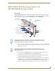
MVP-WDS Wall Docking Station & CB-MVPWDS Rough-In Box Installation MVP-WDS wall-docking stations can be installed either the CB-MVPWDS or other solid surface environment using one of the two mounting options: drywall clips or solid surface screws, as described in the following sub-sections. Installing the CB-MVPWDS Rough-In Box The CB-MVPWDS (FG037-10) is a metallic rough-in box that can be secured to a stud in a pre-wall setting. The MVP-WDS can then installed into the rough-in box.
MVP-WDS Wall Docking Station & CB-MVPWDS Rough-In Box Although there are wiring knockouts are on both sides of the rough-in box, the knockouts on the right side will be used for the MVP-WDS (wall docking station) connectors, so always secure the rough-in box to the stud using the Stud Mounting Holes on the left side of the box. 2. Using either nails or screws, fasten the rough-in box to the stud through the five Stud Fastening Holes. 3.
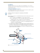
MVP-WDS Wall Docking Station & CB-MVPWDS Rough-In Box Battery Compartment Cover MVP Support Cradle Battery slot 1 Battery slot 2 Cradle Activation pushbutton (located inside Battery Slot #2) Power supply feed Battery Compartment Latch FIG. 5 Cradle activation pushbutton location and cradle angling 4. Close the battery cover and disconnect the power connector to remove power from the unit and maintain the support cradle in the forward position. 5.
MVP-WDS Wall Docking Station & CB-MVPWDS Rough-In Box Faceplate Securing Latches Faceplate Connectors FIG. 7 Faceplate securing latch and connector locations 8. Press down on the Security Latch to allow it to go through the top opening. 9. Grasp the top rim of the faceplate and carefully slide it over the cradle (at an angle) until the faceplate is completely removed from the WDS (FIG. 8). Faceplate securing latches Faceplate FIG.
MVP-WDS Wall Docking Station & CB-MVPWDS Rough-In Box Installing the MVP-WDS in a CB-MVPWDS Rough-In Box The rough-in box must be mounted prior to continuing this section. Refer to the Installing the CB-MVPWDS Rough-In Box section on page 4 for detailed pre-wall installation instructions. The faceplate must be removed prior to any surface installation (see the Removing the MVPWDS Faceplate section on page 5).
MVP-WDS Wall Docking Station & CB-MVPWDS Rough-In Box 3. Using a grounded Phillips-head screwdriver, insert and secure four #6-32 Mounting Screws (not included) into their corresponding holes located along the sides of the MVP-WDS until the WDS is securely fastened to the rough-in box, and is flush against the wall.
MVP-WDS Wall Docking Station & CB-MVPWDS Rough-In Box 2. Thread the USB and Power cables through the surface opening, leaving enough slack in the wiring to accommodate re-positioning of the unit. 3. Connect the 2-pin power connector and USB cables to the WDS. The WDS must be installed with these attached. The USB connectors can be from either a USB extension cable, or a wireless USB RF transmitter.
MVP-WDS Wall Docking Station & CB-MVPWDS Rough-In Box Four notches are required to accommodate the four expansion clips (included) Install the four included drywall clip sets at these locations #6-32 Faceplate Security Screws (2) Die Cut Foam covers (2) Mounting Tab A - Faceplate B - MVP-WDS (Main unit) FIG. 12 MVP-WDS installation configuration for drywall surfaces Replacement drywall clip sets cab be ordered from AMX. 6.
MVP-WDS Wall Docking Station & CB-MVPWDS Rough-In Box 12.70 [323MM] BEZEL OUTLINE .52 [13MM] TYP 11.06 [281MM] FRONT BEZEL OUTLINE 1.19 [30MM] TYP R.13 [3.2MM] MAX RADIUS IN 4 CORNERS THESE 4 HOLES ARE ONLY REQUIRED WHEN MOUNTING UNIT TO A SOLID SURFACE (PODIUM, DESK, ETC). SECURE UNIT WITH #4 SCREWS 7.91 [201MM] 5.54 [141MM] 8.63 [219MM] BEZEL OUTLINE CUTOUT 12.10 [307MM] FIG. 13 MVP-WDS Wall Mount cutout dimensions using solid surface screws 2.
MVP-WDS Wall Docking Station & CB-MVPWDS Rough-In Box 7. Insert and secure four #4-40 Mounting Screws (not included) into their corresponding holes located along the sides of the WDS (using a grounded Phillips-head screwdriver) until the WDS is secured and is flush against the wall. 8. Follow the steps outlined in the Replacing the Faceplate on the MVP-WDS section on page 13 to angle the MVP Support Cradle forward and re-install the faceplate.
MVP-WDS Wall Docking Station & CB-MVPWDS Rough-In Box 7. Apply power to the MVP-WDS by connecting the terminal end of the power cable to the power supply. 8. Press the Cradle Activation pushbutton to cause the MVP Support Cradle to angle backwards and lie flush against the main unit. 9. Remove the two adhesive plastic Die Cut Foam covers (60-5965-47) from the strip included within the Installation Kit bag. 10.
MVP-WDS Wall Docking Station & CB-MVPWDS Rough-In Box Connecting and Using USB Input Devices on the Stations The MVP-WDS can have up to two USB input devices connected for use on the MVP panel’s different firmware and TPD4 panel pages. These input devices can consist of a keyboard and mouse. USB-connected input devices are detected by the docking stations only after they are connected and then power is applied. 1. Remove the power connector from the docking station. 2.
MVP-WDS Wall Docking Station & CB-MVPWDS Rough-In Box 1 - Data - Panel Detect IN 2 - Ground 3 - not used 4 - Ground 5 - not used 6 - Ground 7 - not used 8 - not used 9 - not used 10 - DC Power 11 - Data - Receive 12 - DC Power 13 - Data - Transmit 14 - DC Power 15 - Data - USB Device D16 - Data - Cradle Detect 17 - Data - USB Device D+ 18 - Data - Panel Detect OUT 2 1 18 17 FIG. 16 MVP-TDS Connector Pin locations and Pinout function Securing an MVP Panel to an MVP-WDS 1.
MVP-WDS Wall Docking Station & CB-MVPWDS Rough-In Box On-screen Docking message Docking Status button (illuminates to also give an indication that the panel is properly docked) FIG. 18 System message - panel is properly docked If the MVP is docked properly and communicating, the right LED on the MVP-WDS will remain brightly illuminated. Refer to the LED Pattern Indicators for the MVP-WDS table on page 3 for more information.
MVP-WDS Wall Docking Station & CB-MVPWDS Rough-In Box Undock- String When the MVP is removed from the docking station (undocked), the undock- string is sent to the NetLinx Master. If the panel has no information within the User Access Passwords list, ’none’ is sent as a user. If the undock button on the Protected Setup page is used, ’setup’ is sent as a user. This string can be disabled from within the firmware setup pages.
MVP-WDS Wall Docking Station & CB-MVPWDS Rough-In Box Installing the MVP-WDS-SK Silver Conversion Kit The VP-WDS-SK Silver Conversion Kit (FG5965-22) contains the following components: One Silver Cradle Bezel/Faceplate (60-5965-20SL) One Silver Cradle Pivot (Support Cradle) (60-5965-21SL) One Silver Battery Cover (60-5965-22SL) One securing rare earth magnet (63-5965-02) One securing magnet cup (63-5965-03) One #4-20 Magnet Securing screw (80-0193-01) Two plastic Die Cut Foam covers (60-5965-47) Installati
MVP-WDS Wall Docking Station & CB-MVPWDS Rough-In Box Battery Compartment Cover MVP Support Cradle Die Cut Foam Cover location Cradle Activation pushbutton (located inside Battery Slot #2) Battery Compartment Latch Power supply feed (2-pin 3.5 mm mini-Phoenix) FIG. 19 Cradle activation pushbutton location and cradle angling 7. Disconnect the 2-pin mini-Phoenix connector from the side of the docking station to remove power from the unit and maintain the support cradle in this angled position. 8.
MVP-WDS Wall Docking Station & CB-MVPWDS Rough-In Box Faceplate securing latches Faceplate FIG. 21 Faceplate removal from MVP-WDS As you are removing the faceplate, you will have to press down on the Security Latch to allow a complete removal of the faceplate. 14. Press downward on the Security Latch (towards the pushbutton) to get it to go through the top opening and allow the faceplate’s removal. 15.
MVP-WDS Wall Docking Station & CB-MVPWDS Rough-In Box Attachment screw Gap opening Long Magnetic Phillips-head screwdrivers Support Cradle Pivot movement mechanism FIG. 23 Separating the support cradle from its movement mechanism 4. Carefully remove the cradle pivot’s attachment screw and place it aside for later re-attachment. 5.
MVP-WDS Wall Docking Station & CB-MVPWDS Rough-In Box Circuit board A Circuit board B FIG. 25 Removing the attached circuit boards (A & B) 8. Carefully place the first circuit board aside and rotate the black pivot combo unit over to expose the second circuit board attached to the backside of the unit (B in FIG. 25). 9. Carefully remove this second board by unscrewing the three screws and then gently placing this board aside (B in FIG. 25). 10. Place the black pivot combo unit aside.
MVP-WDS Wall Docking Station & CB-MVPWDS Rough-In Box Silver battery cover (60-5965-22SL) Silver cradle pivot (60-5965-21L) Pivot combo unit (battery cover and pivot) Battery cover guide FIG. 26 Installation of silver cradle pivot and battery cover 5. Use the screwdriver to install one of the previously removed MVP Support Cradle Securing screws to the securing plate (shown in FIG. 24 on page 22). 6. Carefully slide the entire silver battery pivot combo unit into the black WDS metal housing.
MVP-WDS Wall Docking Station & CB-MVPWDS Rough-In Box Open the Battery Compartment by pressing down on the Battery Compartment Latch and then pulling the cover outwards. Press the Cradle Activation pushbutton (the small recessed white button located near the pins in Battery Slot #2) to make the MVP Support Cradle rise upwards. The MVP Support Cradle must be angled upward to allow removal of the faceplate.
MVP-WDS Wall Docking Station & CB-MVPWDS Rough-In Box 26 MVP-WDS Wall Docking Station for MVP Panels
Upgrading the Docking Station Firmware Upgrading the Docking Station Firmware The following accessory devices are firmware upgradeable: MVP-TDS Table Top Docking Station (FG5965-10) MVP-WDS Wall/Flush Mount Docking Station - Black (FG5965-11) MVP-WDS Wall/Flush Mount Docking Station - Silver (FG5965-21) This device is not given a unique device number which would ordinarily appear within the Online Tree tab of NetLinx Studio.
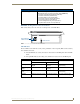
Upgrading the Docking Station Firmware Displays the current docking station firmware version FIG. 2 Batteries page The docking station firmware is shown on the right of the Batteries page. Verify you have downloaded the latest firmware file from www.amx.com and then save the Kit file to your computer. Step 2: Upgrade the Docking Station firmware via USB 1. Configure the panel for a USB Connection Type. 2. Prepare NetLinx Studio for communication to the panel via a Virtual Master.
Upgrading the Docking Station Firmware Selected Docking Station Firmware file Description field for selected Kit file Firmware download status Device and System values must match the System and Device values listed in the Project Navigator window FIG. 3 Send to NetLinx Device dialog (showing docking station firmware update via USB) Firmware upgrades can not be done directly to the docking station but must be routed through the MVP panel. 10. Click the Reboot Device checkbox.
Upgrading the Docking Station Firmware Although firmware upgrades can be done over wireless Ethernet; it is recommended that firmware KIT files be transferred over a direct USB connection and only when the panel is connected to a power supply. If battery power or wireless connection fails during a firmware upgrade, the panel flash file system may become corrupted.
Upgrading the Docking Station Firmware MVP-WDS Wall Docking Station for MVP Panels 31
12/08 ©2008 AMX. All rights reserved. AMX and the AMX logo are registered trademarks of AMX. AMX reserves the right to alter specifications without notice at any time. 93-5965-13 REV E It’s Your World - Take Control™ 3000 RESEARCH DRIVE, RICHARDSON, TX 75082 USA • 800.222.0193 • 469.624.8000 • 469-624-7153 fax • 800.932.6993 technical support • www.amx.