
Specifications


Installation
16
MST-431/MSD-431-L 4.3" Modero S Series® Touch Panels
3. After ensuring proper placement, cut out the mounting surface for the back box, using the MSD-431-L
Installation Template as a guide.
4. Thread the incoming Ethernetfrom their terminal locations through the surface opening (FIG. 13). Leave
enough slack in the wiring to accommodate any re-positioning of the panel.
5. Remove the back box knockouts (FIG. 13) and thread the incoming wiring through the knockout holes.
6. Thread the incoming Ethernet from the surface opening and through the knockouts.
7. Push the back box into the mounting surface. Insure that the locking tabs lie flush against the back box
and that the back box goes freely into the opening.
8. Extend the locking tabs on the sides of the back box by tightening the screws inside the box until snug.
Not all of the tabs must be extended to lock the back box in place, but extending a minimum of the top
and bottom tabs is highly recommended. Apply enough pressure to the screw head to keep the box flush
with the wall: this ensures that the locking tabs will tighten up against the inside of the wall.
The back box is clear to allow visual confirmation that the tabs have been extended and are gripping the
wall, as well as in assisting with removal if necessary.
9. Insert each connector into its corresponding location along the back of the device (FIG. 14).
Using the included template to select the final placement of the back box is highly
recommended. The outside edges of the template are the same dimensions as the
touch panel, which allows you to troubleshoot possible conflicts with wall edges,
doors, and other potential obstacles.
Making sure the actual cutout opening is slightly smaller than the provided
dimensions is highly recommended. This action provides the installer with a margin
for error if the opening needs to be expanded. Too little wall material removed is
always better than too much.
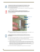
FIG. 13 MSD-431-L Back Box Installation
Knockout
Back Box
Mounting Surface
Locking
Tab
The Micro-USB port cannot be used while the touch panel installed in the back box.
The MSD-431 must be removed from the wall and the back box in order to access the
Micro-USB port.