Operation/Reference Guide MST-431/MSD-431-L 4.3” Modero S Series® Tabletop Touch Panel 4.
AMX Limited Warranty and Disclaimer This Limited Warranty and Disclaimer extends only to products purchased directly from AMX or an AMX Authorized Partner which include AMX Dealers, Distributors, VIP’s or other AMX authorized entity.
AMX Software License and Warranty Agreement • LICENSE GRANT. AMX grants to Licensee the non-exclusive right to use the AMX Software in the manner described in this License. The AMX Software is licensed, not sold. This license does not grant Licensee the right to create derivative works of the AMX Software. The AMX Software consists of generally available programming and development software, product documentation, sample applications, tools and utilities, and miscellaneous technical information.
Table of Contents Table of Contents Introduction ........................................................................................................1 Features .................................................................................................................... 1 MST-431 .............................................................................................................2 Connector Locations ........................................................................................
Table of Contents Downloading firmware .................................................................................................. 25 Appendix: Troubleshooting ..............................................................................27 Overview ................................................................................................................ 27 Panel Doesn’t Respond To Touches ..............................................................................
Introduction Introduction The Modero S Series® line of touch panels is a cousin to the popular Modero X Series, with features optimized for specific needs. For those customers who just want a control touch panel without all of the additional features offered in the Modero X Series, the Modero S Series panels offer AMX engineering quality and industrial design, a more rugged touch interface, secure locking features, and streaming Voice Over Internet Protocol (VoIP) and video.
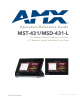
MST-431 MST-431 The Modero S Series is a touch panel family sophisticated enough for room control yet priced right for the most cost sensitive installations including small huddle spaces and dedicated room scheduling applications. The smallest of our Modero S tabletop touch panels, the MST-431 Modero S Series 4.3" Tabletop Touch Panel (FG2265-07) (FIG.
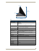
MST-431 Sleep Button 3.21" (84.16 mm) USB Port 3.10" (78.76 mm) FIG. 2 MST-431 side view MST-431 Specifications Power Requirements: PoE (Power over Ethernet), 802.3af, class 2 Power Consumption: • Full-On: 4W • Standby: 2W • Shutdown: 0.6W • •Start-Up Inrush Current: Not applicable due to PoE standard Front Panel Components: Sleep Button: Single button on top of panel for placing panel in sleep mode, for powering off the panel, and for accessing the Settings Pages.
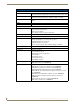
MST-431 MST-431 Specifications (Cont.) Communications: Ethernet: Ethernet: 10/100 port, RJ-45 connector. Supported IP and IP-based protocols: UCP, TCP, ICMP, ICSP, IGMP, DHCP, Telnet, FTP, DNS, RFB (for VNC), HTTP USB: (1) USB host 2.0, Type A port: Firmware upgrade, touch panel file transfer, JPEG image viewer, HID Peripherals, USB audio output for headsets Bluetooth: HID Profile v1.1, Keyboard/Mouse Support, requires MXA-BT Bluetooth Adaptor.
MST-431 Connector Locations With the unit facing you, the single USB port for peripherals is located on the rear right side of the device (FIG. 3). The RJ45 connector for PoE is also located on the back of the device. USB Port RJ-45 Port Speaker FIG. 3 MST-431 USB port location Memory The MST-431 comes with 512 MB of SDRAM and 4 GB of Flash memory, neither of which can be upgraded. A maximum of 2.4 GB is available to the user for projects.
MSD-431-L MSD-431-L The MSD-431-L 4.3" Landscape Wall Mount Touch Panel (FG2265-03) has a sleek style to complement the Modero X Series touch panels, with a new elegant room availability indicator bar and glass mounting option. Now even the smallest, most cost sensitive meeting spaces can benefit from a dedicated scheduling panel without compromising the architectural beauty of the facility, allowing users to view the room schedule at a glance and even reserve the room right from the panel.
MSD-431-L MSD-431-L Specifications Power Requirements: PoE (Power over Ethernet), 802.3af, class 3 Power Consumption: • Full-On: 4W maximum • Standby: 2W • Shutdown: 0.6W • Start-Up Inrush Current: Not applicable due to PoE standard Front Panel Components: LEDs: Red and green LEDs on left and right side of panel, used to signal room availability. Sleep Button: Single button on edge of panel for placing panel in sleep mode, for powering off the panel, and for accessing the Settings Pages.
MSD-431-L MSD-431-L Specifications (Cont.) Weight: Certifications: 0.5 lbs (0.
MST-431/MSD-431-L Features MST-431/MSD-431-L Features Picture View By connecting a USB drive via one of the device’s USB ports (FIG. 3), Picture View allows the MST-431 to access JPEG images on that drive and display them on the touchscreen (FIG. 6). Individual images may be accessed at any time, or the entire collection may be displayed for predetermined times. Picture View may be stopped at any time by removing the USB drive, and the MST-431 will return to its default display page. FIG.
MST-431/MSD-431-L Features Pause/ Resume Stop Random/ A-Z Counter Previous image saved Next image saved Timer FIG. 7 Picture View configuration popup menu The Pause/Resume button allows the display to stop on one particular image. Press it again to resume the display procession. The Next Image Saved button returns the display to the last image uploaded by Page View. If the panel has not accessed all of the images available on a USB drive, Page View will display the last one uploaded to date.
MST-431/MSD-431-L Features Configuration The MST-431 and MSD-431-L are equipped with Settings Pages that allow you to set and configure various features on the panels. For more information on connecting and configuring the touch panels to a network, please refer to the Modero S Series Programming Guide, available at www.amx.com. Bluetooth Support Both the MST-431 and the MSD-431-L allow the use of Bluetooth keyboard and mouse combinations, using HID Profile v1.1.
MST-431/MSD-431-L Features 12 MST-431/MSD-431-L 4.
Installation Installation MST-431 Installation Any USB peripherals (mouse, keyboard, etc.) may be connected to the USB port on the rear of the device (FIG. 8). Updates to the device’s firmware are also made via the USB port.. USB Port Entry for RJ45/ PoE Cable Speaker FIG.
Installation MSD-431-L Installation The MSD-431-L may be installed directly into a solid surface environment, using either solid surface screws or the included locking tabs for different mounting options. Once installed, the MSD-431-L is contained within a clear outer housing known as the back box (FIG. 9). This back box is removed when installing the device into a wall or into a Rough-In Box. Locking tabs FIG.
Installation Sleep Button Back box knockout Locking tabs MSD-431-L (front) Back box knockout FIG. 11 Side view of MSD-431-L In order to guarantee a stable installation of the MSD-431-L, the thickness of the wall material must be a minimum of .50 inches (1.27cm) and a maximum of .875 inches (2.22cm). The mounting surface should also be smooth and flat. The maximum recommended torque to screw in the locking tabs on the plastic back box is 5 IN-LB [56 N-CM].
Installation Using the included template to select the final placement of the back box is highly recommended. The outside edges of the template are the same dimensions as the touch panel, which allows you to troubleshoot possible conflicts with wall edges, doors, and other potential obstacles. 3. After ensuring proper placement, cut out the mounting surface for the back box, using the MSD-431-L Installation Template as a guide.
Installation Top Micro-USB RJ45 Port Port FIG. 14 Rear of the MSD-431-L 10. Test the incoming wiring by attaching the panel connections to their terminal locations and applying power. Verify that the panel is receiving power and functioning properly to prevent repetition of the installation. Do not disconnect the connectors from the touch panel. The unit must be installed with the attached connectors before being inserted into the mounting surface. 11.
Installation If you see a gap between the panel and the back box, or feel any binding while locking down the panel, stop immediately and verify that no cables or other items are in the way. Do not force the panel into position, as this can cause damage to the touch screen or the panel electronics. 12. Reconnect the terminal Ethernet and USB to their respective locations on either the Ethernet port or NetLinx Master.
Configuration and Programming Configuration and Programming Programming the MST-431 and MSD-431-L require the use of the latest versions of NetLinx Studio and TPDesign 4, both available at www.amx.com. Modero S Series Programming Guide Information on Settings pages, panel configuration, and programming is included in the Modero S Series Programming Guide, available at www.amx.com. MST-431/MSD-431-L 4.
Configuration and Programming 20 MST-431/MSD-431-L 4.
Upgrading Firmware Upgrading Firmware Programming the MST-431 and MSD-431-L require the use of the latest versions of NetLinx Studio and TPDesign 4, both available from www.amx.com. Upgrading Firmware via USB stick Firmware and TPDesign 4 file downloads may be made via USB stick. When looking at the device from the front, the MST-431 has one USB port on the rear right of the device (FIG. 3). Since the MSD-431-L uses a Micro-USB connection, you will need an adaptor to connect a USB stick to the device.
Upgrading Firmware FIG. 17 New Firmware installation confirmation dialog box Upgrading from Previous Firmware The MST-431 and MSD-431-L allow the option to revert the device to the previous firmware run before an upgrade. To upgrade the device from previously loaded firmware: 1. From the Settings page, select the Configuration page. 2. From the Configuration page, select Admin. 3. From the Admin Configuration page, select Install Firmware. 4. In the Firmware Installation page, select Previous. 5.
Upgrading Firmware FIG. 19 Previous Firmware installation confirmation dialog box Upgrading Firmware Via NetLinx Studio The MST-431 and MSD-431-L use an Ethernet connection for programming, firmware updates, and touch panel file transfer via NetLinx Studio. If you have access to the panel’s network, you may transfer files directly to the panel through NetLinx Studio Firmware upgrades cannot be made through an Ethernet-connected PC to the touch panel, unless that PC is connected to the panel’s network.
Upgrading Firmware 4. Click on the NetLinx Master radio button from the Platform Selection section. 5. Click on the Virtual Master radio box from the Transport Connection Option section to configure the PC to communicate directly with a panel. Everything else, such as the Authentication, is greyed-out because this connection is not going through the Master’s UI. 6. Click the Edit Settings button on the Communications Settings dialog to open the Virtual NetLinx Master Settings dialog (FIG. 22). FIG.
Upgrading Firmware Virtual Master firmware version and device number Panel firmware version and device number FIG. 23 NetLinx Workspace window (showing panel connection via a Virtual NetLinx Master) Downloading firmware The panel-specific firmware is shown on the right of the listed panel. Download the latest firmware file from www.amx.com and then save the Kit file to your computer. Note that each Kit file is intended for download to its corresponding panel.
Upgrading Firmware FIG. 25 Browse for Folder window 7. Click the Reboot Device checkbox if it is not already checked. This causes the touch panel to reboot after the firmware update process is complete. 8. Click Send to begin the transfer. The file transfer progress is indicated on the bottom-right of the dialog. 9. After the file transfer is complete, the panel will automatically reboot. 10. After the panel has finished rebooting, right-click the associated System number and select Refresh System.
Appendix: Troubleshooting Appendix: Troubleshooting Overview This section describes the solutions to possible hardware/firmware issues that could arise during the common operation of a Modero S touch panel. Panel Doesn’t Respond To Touches Symptom: The device either does not respond to touches on the touch screen or does not register the touch as being in the correct area of the screen. If the screen is off: The device may be in Display Sleep Mode. Press and hold the Sleep button to wake up the panel.
Appendix: Troubleshooting 28 MST-431/MSD-431-L 4.
Appendix - Troubleshooting MST-431/MSD-431-L 4.
AMX. All rights reserved. AMX and the AMX logo are registered trademarks of AMX. AMX reserves the right to alter specifications without notice at any time. ©2012 7/2013 It’s Your World - Take Control™ 3000 RESEARCH DRIVE, RICHARDSON, TX 75082 USA • 800.222.0193 • 469.624.8000 • 469-624-7153 fax • 800.932.6993 technical support • www.amx.