
Instruction manual


Installation
12
MST-431/MSD-431-L 4.3" Modero S Series® Touch Panels
4. Thread the incoming Ethernet from their terminal locations through the surface opening (FIG. 10). Leave enough
slack in the wiring to accommodate any re-positioning of the panel.
5. Remove the back box knockouts (FIG. 10) and thread the incoming wiring through the knockout holes.
6. Thread the incoming Ethernet from the surface opening and through the knockouts.
7. Push the back box into the mounting surface. Insure that the locking tabs lie flush against the back box and that the
back box goes freely into the opening.
8. Extend the locking tabs on the sides of the back box by tightening the screws inside the box until snug. Not all of
the tabs must be extended to lock the back box in place, but extending a minimum of the top and bottom tabs is
highly recommended. Apply enough pressure to the screw head to keep the box flush with the wall: this ensures that
the locking tabs will tighten up against the inside of the wall.
The back box is clear to allow visual confirmation that the tabs have been extended and are gripping the wall, as
well as in assisting with removal if necessary.
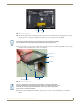
9. Insert each connector into its corresponding location along the back of the device (FIG. 11).
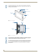
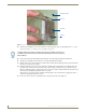
FIG. 10 MSD-431-L Back Box Installation
Knockout
Back Box
Mounting Surface
Locking
Tab
The Micro-USB port cannot be used while the touch panel installed in the back box.
The MSD-431 must be removed from the wall and the back box in order to access the
Micro-USB port.