Instruction Manual MST-431/MSD-431-L 4.3” Modero S Series® Tabletop Touch Panel 4.
AMX Limited Warranty and Disclaimer This Limited Warranty and Disclaimer extends only to products purchased directly from AMX or an AMX Authorized Partner which include AMX Dealers, Distributors, VIP’s or other AMX authorized entity.
Table of Contents Table of Contents MST-431/MSD-431-L 4.3" Modero S Series® .....................................................1 MST-431 ....................................................................................................................1 MST-431 Specifications ................................................................................................. 2 MSD-431-L ................................................................................................................
Table of Contents ii MST-431/MSD-431-L 4.
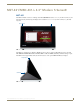
MST-431/MSD-431-L 4.3" Modero S Series® MST-431/MSD-431-L 4.3" Modero S Series® MST-431 The MST-431 Modero S Series 4.3" Tabletop Touch Panel (FG2265-07) features a 5" x 3.4" (128 mm x 87 mm), 6" (152 mm) diagonal 6.0" (152 mm) diagonal display, with a viewable area of 3.7" x 2.1" (95 mm x 54 mm), 4.3" (109 mm) diagonal. Sleep Button Microphone FIG.
MST-431/MSD-431-L 4.3" Modero S Series® MST-431 Specifications MST-431 Specifications DIMENSIONS (HWD) 3 1/4" x 5 1/16" x 3 1/8" (82 mm x 128 mm x 79 mm) WEIGHT 0.9 lbs (.4 Kg) POWER CONSUMPTION • Full-On: 4 W • Typical: 3 W • Standby: 2 W • Shutdown: 0.7 W • Start-Up Inrush Current: Not applicable due to PoE standard EXTERNAL POWER SUPPLY REQUIRED Optimal performance requires use of one of the following AMX PoE power supplies (not included): • PS-POE-AF-TC, PoE Injector, 802.
MST-431/MSD-431-L 4.3" Modero S Series® MST-431 Specifications (Cont.) AUDIO • Microphone: -42 dB ±3 dB sensitivity FET microphone • Speakers: 4 ohm, 1.5 Watt, 500 Hz cutoff frequency • Supported Audio Codecs: MP2 Layer I and II, MP3 (8 kHz, 11.025 kHz, 12 kHz, 16 kHz, 22.05 kHz, 24 kHz, 32 kHz, 44.1 kHz, 48 kHz) AAC-LC (8 kHz, 96 kHz) G.
MST-431/MSD-431-L 4.3" Modero S Series® MSD-431-L The MSD-431-L 4.3" Landscape Wall Mount Touch Panel (FG2265-03) features a 35" x 3.4" (128 mm x 87 mm), 6" (152 mm) diagonal display, with a viewable area of 3.7" x 2.1" (95 mm x 54 mm), 4.3" (109 mm) diagonal. The MSD-431 communicates via Ethernet (10/100 port, RJ-45 connector, supported IP and IP-based protocols: UCP, TCP, ICMP, ICSP, IGMP, DHCP, Telnet, FTP, DNS, RFB for VNC, and HTTP) and USB (1 USB host 2.0, Type A port and 1 Micro-USB device port).
MST-431/MSD-431-L 4.3" Modero S Series® MSD-431-L Specifications (Cont.) TOUCH SCREEN DISPLAY • Display Type: TFT Active Matrix Color LCD • Display Size (WH): Landscape: 5" x 3.4" (128 mm x 87 mm), 6" (152 mm) diagonal • Viewable Area (WH): Landscape: 3.7" x 2.1" (95 mm x 54 mm), 4.3" (109 mm) diagonal • Resolution: Landscape: 480x272 • Aspect Ratio: Landscape: 16:9 • Brightness: 350 cd/m2 • Contrast Ratio: 600:1 • Color Depth: 16.
MST-431/MSD-431-L 4.3" Modero S Series® MSD-431-L Specifications (Cont.) ENVIRONMENTAL • Temperature (Operating): 32° F to 104° F (0° C to 40° C) • Temperature (Storage): 4° F to 140° F (-20° C to 60° C) • Humidity (Operating): 20% to 85% RH • Humidity (Storage): 5% to 85% RH • Power ("Heat") Dissipation: On: 13.6 BTU/hr Standby: 10.9 BTU/hr INCLUDED ACCESSORIES MSD-431-L Installation Template (68-2265-01) OPTIONAL ACCESSORIES • MSA-MMK-43, Multi Mount Kit, 4.
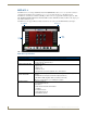
MST-431/MSD-431-L 4.3" Modero S Series® Pause/ Resume Stop Random / A-Z Counter Previous image Timer Next image FIG. 4 Picture View configuration popup menu 3. On the leftmost amber button, select between Rand (images display at random) and A-Z (images display in alphabetical order based on the name of the file). 4. The four gray buttons allow scrolling through saved images and the rate of display: The Previous Image Saved button returns the display to the first image uploaded by Page View.
MST-431/MSD-431-L 4.3" Modero S Series® Configuration The MST-431 and MSD-431-L are equipped with Settings Pages that allow you to set and configure various features on the panels. For more information on connecting and configuring the touch panels to a network, please refer to the Modero S Series Programming Guide, available at www.amx.com. Bluetooth Support Both the MST-431 and the MSD-431-L allow the use of Bluetooth keyboard and mouse combinations, using HID Profile v1.1.
Installation Installation MST-431 Installation Any USB peripherals (mouse, keyboard, etc.) may be connected to the USB port on the rear of the device (FIG. 5). Updates to the device’s firmware are also made via the USB port. USB Port RJ-45 Port Speaker FIG.
Installation For typical mounting surfaces, such as drywall, use the locking tabs as the primary method for securing the back box to the surface. For thin walls or solid surfaces, use mounting screws (not included). Locking tab Back box knockout MSD-431-L (front) Back box FIG. 7 Side view of MSD-431-L Sleep Button Back box knockout Locking tabs MSD-431-L (front) Back box knockout FIG.
Installation To install the back box: 1. Prepare the area by removing any screws or nails from the drywall before beginning the cutout process. 2. For best results, use the MSD-431-L Installation Template (68-2265-01) to ensure proper placement (FIG. 9). The template is marked to ensure that the touch panel and back box are properly aligned. 4.45" (11.30 cm) 2.65" (6.73 cm) FIG.
Installation Mounting Surface Knockout Back Box Locking Tab FIG. 10 MSD-431-L Back Box Installation 4. Thread the incoming Ethernet from their terminal locations through the surface opening (FIG. 10). Leave enough slack in the wiring to accommodate any re-positioning of the panel. The Micro-USB port cannot be used while the touch panel installed in the back box. The MSD-431 must be removed from the wall and the back box in order to access the Micro-USB port. 5. Remove the back box knockouts (FIG.
Installation Micro-USB RJ45 Port Port FIG. 11 Rear of the MSD-431-L 10. Test the incoming wiring by attaching the panel connections to their terminal locations and applying power. Verify that the panel is receiving power and functioning properly to prevent repetition of the installation. Do not disconnect the connectors from the touch panel. The unit must be installed with the attached connectors before being inserted into the mounting surface. 11.
Installation Uninstalling the MSD-431-L The MSD-431-L is held in place to the back box via latch hooks and clips on the back box (FIG. 12), securing it to the mounting surface. In certain circumstances, such as firmware updates or other maintenance that requires accessing the device’s Micro-USB ports the device may need to be removed from the back box. The clips that lock down the MSD431-L’s bottom edge may be unlatched in order to remove the device from the mounting surface.
Configuration and Programming Configuration and Programming Programming the MST-431 and MSD-431-L require the use of the latest versions of NetLinx Studio and TPDesign 4, both available at www.amx.com. Modero S Series Programming Guide Information on Settings pages, panel configuration, and programming is included in the Modero S Series Programming Guide, available at www.amx.com. MST-431/MSD-431-L 4.
Configuration and Programming 16 MST-431/MSD-431-L 4.
Upgrading Firmware Upgrading Firmware Programming the MST-431 and MSD-431-L require the use of the latest versions of NetLinx Studio and TPDesign 4, both available from www.amx.com. Upgrading Firmware via USB stick Firmware and TPDesign 4 file downloads may be made via USB stick. When looking at the device from the front, the MST-431 has one USB port on the rear right of the device. Since the MSD-431-L uses a Micro-USB connection, you will need an adapter to connect a USB stick to the device.
Upgrading Firmware FIG. 14 New Firmware installation confirmation dialog box 9. The touch panel will now prompt you to remove the USB stick to continue. When the USB stick is removed, the touch panel will reboot. Upgrading from Previous Firmware The MST-431 and MSD-431-L allow the option to revert the device to the previous firmware run before an upgrade. To upgrade the device from previously loaded firmware: 1. From the Settings page, select the Configuration page. 2.
Upgrading Firmware FIG. 16 Previous Firmware installation confirmation dialog box 6. If you choose Yes, the device will retrieve the files and then reboot. Upgrading Firmware Via NetLinx Studio The MST-431 and MSD-431-L use an Ethernet connection for programming, firmware updates, and touch panel file transfer via NetLinx Studio.
Upgrading Firmware FIG. 18 Communications Settings dialog box 4. Click on the NetLinx Master radio button from the Platform Selection section. 5. Click on the Virtual Master radio box from the Transport Connection Option section to configure the PC to communicate directly with a panel. Everything else, such as the Authentication, is disabled because this connection is not going through the Master’s UI. 6.
Upgrading Firmware Viewing devices on the Virtual System 1. After the Communication Verification dialog window verifies active communication between the Virtual Master and the panel, click the OnLine Tree tab in the Workspace window (FIG. 20) to view the devices on the Virtual System. The default System value is 1. 2. Right-click on the System entry (FIG. 20) and select Refresh System to re-populate the list. Verify the panel appears in the OnLine Tree tab of the Workspace window.
Upgrading Firmware FIG. 21 Send to NetLinx Device dialog window 4. Select the appropriate Kit file from within the Browse for Folder window (FIG. 22). FIG. 22 Browse for Folder window 5. Select the panel’s Kit file from the Files section. 6. Enter the Device value associated with the panel and the System number associated with the Master (listed in the OnLine Tree tab of the Workspace window). The Port field is greyed-out. 7. Click the Reboot Device checkbox if it is not already checked.
Appendix: Troubleshooting Appendix: Troubleshooting Overview This section describes the solutions to possible hardware/firmware issues that could arise during the common operation of a Modero S touch panel. Panel Doesn’t Respond To Touches Symptom: The device either does not respond to touches on the touch screen or does not register the touch as being in the correct area of the screen. If the screen is off: The device may be in Display Sleep Mode. Press and hold the Sleep button to wake up the panel.
In the ever-changing AV industry, continual education is key to success. AMX University is dedicated to ensuring that you have the opportunity to gather the information and experience you need to deliver strong AMX solutions. Plus, AMX courses also help you earn CEDIA, NSCA, InfoComm, and AMX continuing education units (CEUs).