
Instruction manual


Wiring and Device Connections
25
Enova DVX-2150HD/2155HD All-in-One Presentation Switcher Operation/Reference Guide
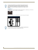
RELAYS (PORT 4)
You can connect up to four independent external relay devices to the Relay connectors on the device (FIG. 38). When a
relay is "OFF", terminals A and B are open-circuit. When a relay is "ON", terminals A and B are shorted together.
Each relay is isolated and normally open.
A metal commoning strip is supplied with each device to simplify the connection of multiple relays to a
common reference if needed.
4-channel single-pole single-throw relay ports
Each relay is independently controlled
Supports up to 4 independent external relay devices
Channel range = 1-4
Each relay can switch up to 24 VDC or 28 VAC peak @ 1 A
One 8-pin 3.5mm mini-Phoenix (female) connector provides relay termination
I/O (PORT 9)
The I/O port (FIG. 39) responds to switch closures and voltage level (high/low) changes, or can be used for logic-level
outputs.
A contact closure between the GND and an I/O port is detected as a Push.
When used for voltage inputs, the I/O port detects a low signal (0 - 1.5 VDC) as a Push, and a high signal (3.5
- 5 VDC) as a Release (this I/O port uses 5V logic but can handle up to 12V without harm).
When used for outputs, the I/O port acts as a switch to GND and is rated for 200mA @ 12 VDC.
The PWR pin provides +12 VDC @ 200 mA and is designed as a power output for the PCS Power Current
Sensors, VSS2 Video Sync Sensors (or equivalent).
The GND connector is a common ground and is shared by all I/O ports.
The input format is software selectable with interactive power sensing for IR ports.
Channel range = 1-8
One 10-pin 3.5mm mini-Phoenix (female) connector provides I/O connection.
FIG. 38 RELAYS connectors
FIG. 39 I/O connectors