
Instruction manual


Wiring and Device Connections
20
Enova DVX-2150HD/2155HD All-in-One Presentation Switcher Operation/Reference Guide
HDMI INPUTS (3-6)
The four HDMI INPUT connectors (ports 3-6) on the rear panel are used to connect source input devices to the
DVX-2150HD-SP (FIG. 30). The DVX-2150HD-SP routes digital video and audio from connected source input devices
to the connected output devices. These ports support HDMI (with 3D and Deep Color) and HDCP.
The DVX-2155HD-SP has only two HDMI INPUT connectors (ports 3 and 4). Ports 5 and 6 are DXLink INPUT
connectors. See the DXLink INPUTS (5-6) section on page 21 for more information.
The DVX-2110HD has only two HDMI INPUT connectors (ports 3 and 4), and no DXLink INPUT connectors.
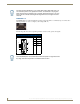
The following table describes the pinout configuration of the HDMI INPUTS connectors:
FIG. 31 displays the pin locations for the HDMI INPUTS:
FIG. 30 HDMI INPUTS connectors
HDMI INPUT Connectors - Pinouts and Signals
Pin Signal Pin Signal
1 TMDS Data 2+ 11 TMDS Clock Shield
2 TMDS Data 2 Shield 12 TMDS Clock-
3 TMDS Data 2- 13 CEC
4 TMDS Data 1+ 14 Reserved, HEC Data
5 TMDS Data 1 Shield 15 SCL
6 TMDS Data 1- 16 SDA
7 TMDS Data 0+ 17 DDC/CEC/HEC Ground
8 TMDS Data 0 Shield 18 +5V Power (max 50mA)
9 TMDS Data 0- 19 Hot Plug Detect, HEC Data+
10 TMDS Clock+
FIG. 31
HDMI pinouts