
Wireless Touch Panel with Intercom Reference Guide

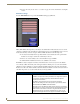
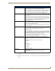
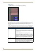
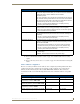

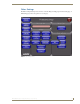
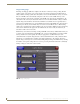
Table Of Contents
- MVP-8400iModero® ViewPoint® Wireless Touch Panel with Intercom
- MVP-8400i Modero Viewpoint Wireless Touch Panel With Intercom
- MVP-BP Power Pack
- NXA-CFSP Compact Flash
- Wireless Interface Cards
- Configuring Communications
- Modero Setup and System Settings
- Wireless Settings Page - Wireless Access Overview
- Configuring a Wireless Network Access
- Step 1: Configure the Panel’s Wireless IP Settings
- Step 2: Configure the Card’s Wireless Security Settings
- Step 3: Choose a Master Connection Mode
- Using G4 Web Control to Interact with a G4 Panel
- Using your NetLinx Master to control the G4 panel
- Upgrading MVP Firmware
- Setup Pages
- Navigation Buttons
- Setup Pages
- Information
- Protected Setup Pages
- Protected Setup Navigation Buttons
- G4 Web Control Page
- Calibration Page
- Wireless Settings Page
- Wireless Security Page
- Open (Clear Text) Settings
- Static WEP Settings
- WPA-PSK Settings
- EAP-LEAP Settings
- EAP-FAST Settings
- EAP-PEAP Settings
- EAP-TTLS Settings
- EAP-TLS Settings
- Client certificate configuration
- System Settings Page
- Other Settings
- Tools
- Programming
- Panel Calibration
- Appendix A: Text Formatting
- Appendix B - Wireless Technology
- Appendix C: Troubleshooting
- Checking AMX USBLAN device connections via Windows Device Manager
- Checking AMX USBLAN device connections via NetLinx Studio
- USB Driver
- Panel Not in Listed As a Connected Device
- Connection Status
- Panel Doesn’t Respond To Touches
- Batteries Will Not Hold Or Take A Charge
- Modero Panel Isn’t Appearing In The Online Tree Tab
- MVP Can’t Obtain a DHCP Address
- My WEP Doesn’t Seem To Be Working
- NetLinx Studio Only Detects One Of My Connected Masters
- Can’t Connect To a NetLinx Master
- Only One Modero Panel In My System Shows Up
- Panel Behaves Strangely After Downloading A Panel File Or Firmware
- Panel Fails to Charge in MVP-WDS
Setup Pages
87
MVP-8400i Modero Viewpoint Wireless Touch Panels
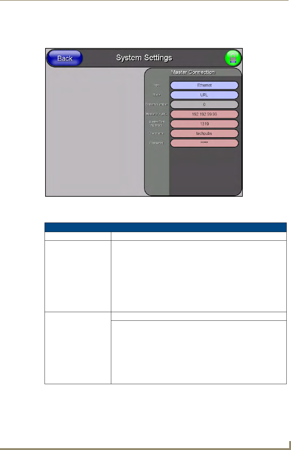
System Settings Page
The System Settings page (FIG. 66) displays sets the NetLinx Master’s communication settings.
The elements of this page include:
FIG. 66 System Settings page
System Settings Page Elements
Back: Saves all changes and returns to the previous page.
Connection Status icon: The icon in the upper-right corner of each Setup page shows online/offline state
of the panel to the master.
• Bright red - disconnected
• Bright green - connected. Blinks when a blink message is received to dark
green every 5 seconds for half a second then go back to bright green.
• Bright yellow - panel missed a blink message from the master. It will remain
yellow for 3 missed blink messages and then turn red. It will return to green
when a blink message is received.
Note: a Lock appears on the icon if the panel is connected to a secured NetLinx
Master.
Master Connection: Sets the NetLinx Master communication values:
Type Sets the NetLinx Master to communicate with the panel via either USB or
Ethernet. This is based on the cable connection from the rear.
Note: ICSNet is not a supported option on this panel.
• Ethernet is a CAT-5 cable (10/100Base T terminated in an RJ-45 connector)
used to network computers together and is used in most LAN (local area
networks). This description is also used to refer to both wired and wireless
communication.
• USB option cannot be used on Modero panels which are not equipped with a
rear USB port.