
Wireless Touch Panel with Intercom Reference Guide
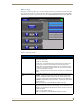
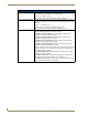
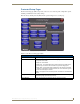
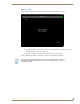
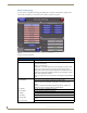
Table Of Contents
- MVP-8400iModero® ViewPoint® Wireless Touch Panel with Intercom
- MVP-8400i Modero Viewpoint Wireless Touch Panel With Intercom
- MVP-BP Power Pack
- NXA-CFSP Compact Flash
- Wireless Interface Cards
- Configuring Communications
- Modero Setup and System Settings
- Wireless Settings Page - Wireless Access Overview
- Configuring a Wireless Network Access
- Step 1: Configure the Panel’s Wireless IP Settings
- Step 2: Configure the Card’s Wireless Security Settings
- Step 3: Choose a Master Connection Mode
- Using G4 Web Control to Interact with a G4 Panel
- Using your NetLinx Master to control the G4 panel
- Upgrading MVP Firmware
- Setup Pages
- Navigation Buttons
- Setup Pages
- Information
- Protected Setup Pages
- Protected Setup Navigation Buttons
- G4 Web Control Page
- Calibration Page
- Wireless Settings Page
- Wireless Security Page
- Open (Clear Text) Settings
- Static WEP Settings
- WPA-PSK Settings
- EAP-LEAP Settings
- EAP-FAST Settings
- EAP-PEAP Settings
- EAP-TTLS Settings
- EAP-TLS Settings
- Client certificate configuration
- System Settings Page
- Other Settings
- Tools
- Programming
- Panel Calibration
- Appendix A: Text Formatting
- Appendix B - Wireless Technology
- Appendix C: Troubleshooting
- Checking AMX USBLAN device connections via Windows Device Manager
- Checking AMX USBLAN device connections via NetLinx Studio
- USB Driver
- Panel Not in Listed As a Connected Device
- Connection Status
- Panel Doesn’t Respond To Touches
- Batteries Will Not Hold Or Take A Charge
- Modero Panel Isn’t Appearing In The Online Tree Tab
- MVP Can’t Obtain a DHCP Address
- My WEP Doesn’t Seem To Be Working
- NetLinx Studio Only Detects One Of My Connected Masters
- Can’t Connect To a NetLinx Master
- Only One Modero Panel In My System Shows Up
- Panel Behaves Strangely After Downloading A Panel File Or Firmware
- Panel Fails to Charge in MVP-WDS
Setup Pages
64
MVP-8400i Modero Viewpoint Wireless Touch Panels
Protected Setup Navigation Buttons
The Protected Setup Navigation Buttons (FIG. 53) appear on the left of the panel screen when the
Protected Setup page is currently active.
Protected Setup Page (Cont.)
Options: • Function Show - toggles the display of the channel port, channel code, level
port and level code on all touch panel buttons (see
FIG. 52).
• Page Tracking - toggles the page tracking function. When enabled, the panel
reports page data to the NetLinx Master.
• Telnet - enables/disables the panel’s telnet server (to allow direct telnet
communication to the panel).
• Front Button Setup Access - activates the two lower buttons on the front of
the panel for accessing the Setup and Calibration pages (see
FIG. 42 on
page 51). The default setting is On.
- Press and hold these buttons for 3 seconds to access the Setup page.
- Press and hold these buttons for 6 seconds to access the Calibration page.
System Recovery: • Reset System Settings - deletes all of the current configuration parameters
on the panel (including IP Addresses, Device Number assignments,
Passwords, and other presets). This option invokes a Confirmation dialog,
prompting you to confirm your selection before resetting the panel.
System Recovery (Cont.): • Remove User Pages - allows you remove all TPD4 touch panel pages
currently on the panel, including the pre-installed AMX Demo pages. This
option invokes a Confirmation dialog, prompting you to confirm your selection
before removing the panel pages.
Note that the YES button on the Confirmation dialog is disabled for 5 seconds
as additional protection against accidentally resetting the panel or removing
the panel pages.
Reboot Panel: Pressing this button causes the panel to reboot after saving any changes.
Docking Station: • Dock Status - illuminates when the MVP is docked and communicating with
the Docking Station.
• Undock Panel - forces the docking station to release the MVP without
requiring a User Access username or password.
• Disable Docking Station LED - disables the display of the LEDs on the
docking station.
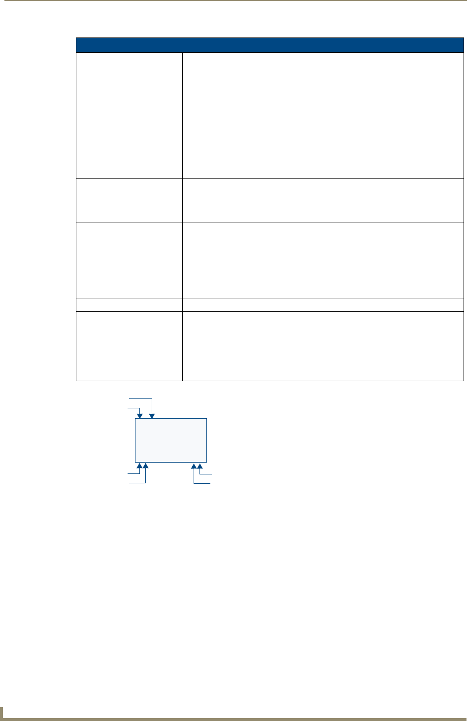
FIG. 52 Function Show example
Channel Code
3,132
2,8 3,50
Channel Port
Level Port
Address Port
Address Code
Channel Code
BUTTON