
Wireless Touch Panel with Intercom Reference Guide
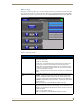
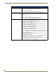
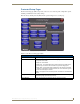
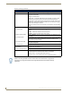
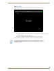
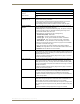
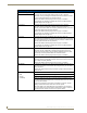
Table Of Contents
- MVP-8400iModero® ViewPoint® Wireless Touch Panel with Intercom
- MVP-8400i Modero Viewpoint Wireless Touch Panel With Intercom
- MVP-BP Power Pack
- NXA-CFSP Compact Flash
- Wireless Interface Cards
- Configuring Communications
- Modero Setup and System Settings
- Wireless Settings Page - Wireless Access Overview
- Configuring a Wireless Network Access
- Step 1: Configure the Panel’s Wireless IP Settings
- Step 2: Configure the Card’s Wireless Security Settings
- Step 3: Choose a Master Connection Mode
- Using G4 Web Control to Interact with a G4 Panel
- Using your NetLinx Master to control the G4 panel
- Upgrading MVP Firmware
- Setup Pages
- Navigation Buttons
- Setup Pages
- Information
- Protected Setup Pages
- Protected Setup Navigation Buttons
- G4 Web Control Page
- Calibration Page
- Wireless Settings Page
- Wireless Security Page
- Open (Clear Text) Settings
- Static WEP Settings
- WPA-PSK Settings
- EAP-LEAP Settings
- EAP-FAST Settings
- EAP-PEAP Settings
- EAP-TTLS Settings
- EAP-TLS Settings
- Client certificate configuration
- System Settings Page
- Other Settings
- Tools
- Programming
- Panel Calibration
- Appendix A: Text Formatting
- Appendix B - Wireless Technology
- Appendix C: Troubleshooting
- Checking AMX USBLAN device connections via Windows Device Manager
- Checking AMX USBLAN device connections via NetLinx Studio
- USB Driver
- Panel Not in Listed As a Connected Device
- Connection Status
- Panel Doesn’t Respond To Touches
- Batteries Will Not Hold Or Take A Charge
- Modero Panel Isn’t Appearing In The Online Tree Tab
- MVP Can’t Obtain a DHCP Address
- My WEP Doesn’t Seem To Be Working
- NetLinx Studio Only Detects One Of My Connected Masters
- Can’t Connect To a NetLinx Master
- Only One Modero Panel In My System Shows Up
- Panel Behaves Strangely After Downloading A Panel File Or Firmware
- Panel Fails to Charge in MVP-WDS
Setup Pages
62
MVP-8400i Modero Viewpoint Wireless Touch Panels
Batteries Page (Cont.)
Low Battery Warning: The UP/DN buttons adjust the time value (in minutes) available on the battery
(for use) before the panel displays a low battery warning.
Range - 10 - 45, default = 15 min.
Note: This field applies to MVP-BP batteries installed in the panel.
Very Low Battery Warning: The UP/DN buttons adjust the time value (in minutes) available on the battery
before the panel displays a very low battery warning (indicating near-term panel
shutdown).
• Range = 3 - 15, default = 5 min.
• This value cannot exceed the Low Battery Warning value.
Note: This field applies to MVP-BP batteries installed in the panel.
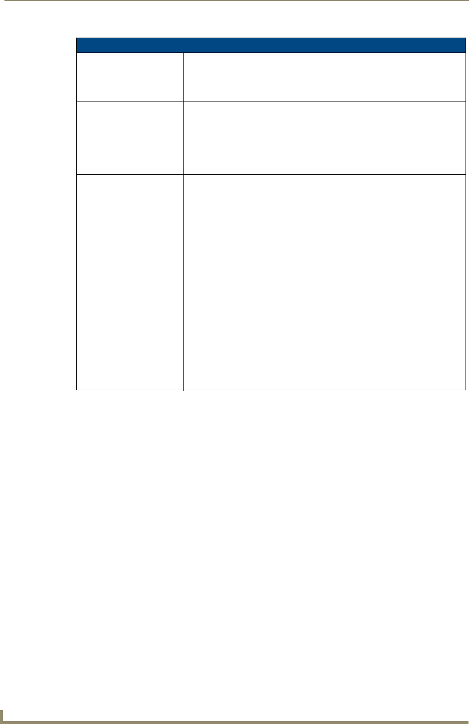
Battery Status: • The Combined Charge Status bargraph indicates the combined power
charge available from batteries installed in the panel.
• The Battery One Charge Status bargraph indicates the power charge
available on the Slot 1 battery (in the panel).
• The Battery Two Charge Status bargraph indicates the power charge
available on the Slot 2 battery (in the panel).
• The Battery Dock 1 Charge Status bargraph indicates the power charge
available on the docking station’s battery #1.
• The Battery Dock 2 Charge Status bargraph indicates the power charge
available on the docking station’s battery #2.
Note: If no batteries are being charged within the docking station’s battery com-
partments, or the MVP is not connected to a docking station; both Battery Dock
Charge Status fields are left blank.
• The Docking Station Version field indicates the firmware version currently
installed on the docking station.
• The Battery Level Port field indicates the port being used to report charge
status levels back to the NetLinx Master (set in TPDesign4).
• The Battery Level field indicates the level being used to report status levels
back to the NetLinx Master (set in TPDesign4).