
Wireless Touch Panel with Intercom Reference Guide
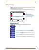
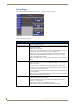
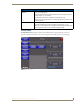
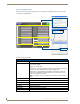
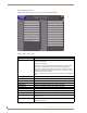
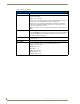

Table Of Contents
- MVP-8400iModero® ViewPoint® Wireless Touch Panel with Intercom
- MVP-8400i Modero Viewpoint Wireless Touch Panel With Intercom
- MVP-BP Power Pack
- NXA-CFSP Compact Flash
- Wireless Interface Cards
- Configuring Communications
- Modero Setup and System Settings
- Wireless Settings Page - Wireless Access Overview
- Configuring a Wireless Network Access
- Step 1: Configure the Panel’s Wireless IP Settings
- Step 2: Configure the Card’s Wireless Security Settings
- Step 3: Choose a Master Connection Mode
- Using G4 Web Control to Interact with a G4 Panel
- Using your NetLinx Master to control the G4 panel
- Upgrading MVP Firmware
- Setup Pages
- Navigation Buttons
- Setup Pages
- Information
- Protected Setup Pages
- Protected Setup Navigation Buttons
- G4 Web Control Page
- Calibration Page
- Wireless Settings Page
- Wireless Security Page
- Open (Clear Text) Settings
- Static WEP Settings
- WPA-PSK Settings
- EAP-LEAP Settings
- EAP-FAST Settings
- EAP-PEAP Settings
- EAP-TTLS Settings
- EAP-TLS Settings
- Client certificate configuration
- System Settings Page
- Other Settings
- Tools
- Programming
- Panel Calibration
- Appendix A: Text Formatting
- Appendix B - Wireless Technology
- Appendix C: Troubleshooting
- Checking AMX USBLAN device connections via Windows Device Manager
- Checking AMX USBLAN device connections via NetLinx Studio
- USB Driver
- Panel Not in Listed As a Connected Device
- Connection Status
- Panel Doesn’t Respond To Touches
- Batteries Will Not Hold Or Take A Charge
- Modero Panel Isn’t Appearing In The Online Tree Tab
- MVP Can’t Obtain a DHCP Address
- My WEP Doesn’t Seem To Be Working
- NetLinx Studio Only Detects One Of My Connected Masters
- Can’t Connect To a NetLinx Master
- Only One Modero Panel In My System Shows Up
- Panel Behaves Strangely After Downloading A Panel File Or Firmware
- Panel Fails to Charge in MVP-WDS
Setup Pages
53
MVP-8400i Modero Viewpoint Wireless Touch Panels
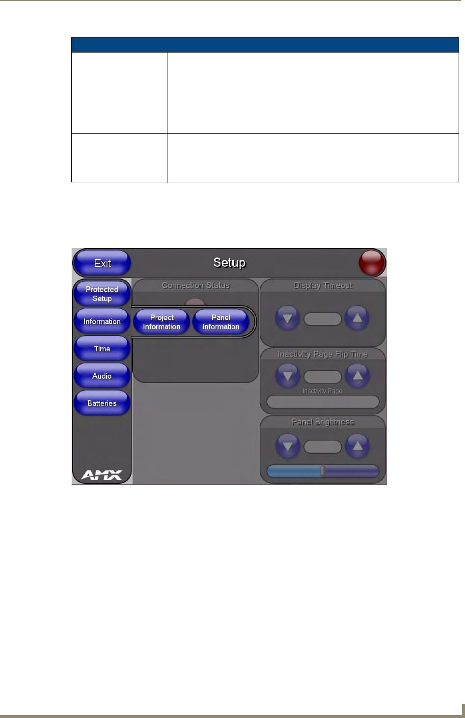
Information
The Information button provides a menu to select either the Project Information Page section on
page 54 or the Panel Information Page section on page 56. Select either option to access that page.
Setup Page (Cont.)
Inactivity Page Flip
Timeout:
Indicates the length of time that the panel can remain idle before automatically flip-
ping to a pre-selected page.
• Press the UP/DN buttons to increase/decrease the Inactivity Page Flip Timeout
setting. Range = 0 - 240 (minutes).
• Set the timeout value to zero to disable Inactivity Page Flip mode.
Note: The touch panel page used for the Inactivity page flip is shown within a small
Inactivity Page field.
Panel Brightness: Sets the display brightness level of the panel.
• Press the UP/DN buttons to adjust the brightness level. Range = 0 - 100.
Note: The on-screen bargraph can be dragged to adjust the brightness level which
is then reflected as a numeric value in the Panel Brightness field.
FIG. 45 Information menu