
Wireless Touch Panel with Intercom Reference Guide
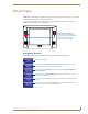
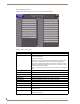
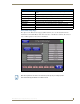
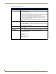

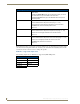
Table Of Contents
- MVP-8400iModero® ViewPoint® Wireless Touch Panel with Intercom
- MVP-8400i Modero Viewpoint Wireless Touch Panel With Intercom
- MVP-BP Power Pack
- NXA-CFSP Compact Flash
- Wireless Interface Cards
- Configuring Communications
- Modero Setup and System Settings
- Wireless Settings Page - Wireless Access Overview
- Configuring a Wireless Network Access
- Step 1: Configure the Panel’s Wireless IP Settings
- Step 2: Configure the Card’s Wireless Security Settings
- Step 3: Choose a Master Connection Mode
- Using G4 Web Control to Interact with a G4 Panel
- Using your NetLinx Master to control the G4 panel
- Upgrading MVP Firmware
- Setup Pages
- Navigation Buttons
- Setup Pages
- Information
- Protected Setup Pages
- Protected Setup Navigation Buttons
- G4 Web Control Page
- Calibration Page
- Wireless Settings Page
- Wireless Security Page
- Open (Clear Text) Settings
- Static WEP Settings
- WPA-PSK Settings
- EAP-LEAP Settings
- EAP-FAST Settings
- EAP-PEAP Settings
- EAP-TTLS Settings
- EAP-TLS Settings
- Client certificate configuration
- System Settings Page
- Other Settings
- Tools
- Programming
- Panel Calibration
- Appendix A: Text Formatting
- Appendix B - Wireless Technology
- Appendix C: Troubleshooting
- Checking AMX USBLAN device connections via Windows Device Manager
- Checking AMX USBLAN device connections via NetLinx Studio
- USB Driver
- Panel Not in Listed As a Connected Device
- Connection Status
- Panel Doesn’t Respond To Touches
- Batteries Will Not Hold Or Take A Charge
- Modero Panel Isn’t Appearing In The Online Tree Tab
- MVP Can’t Obtain a DHCP Address
- My WEP Doesn’t Seem To Be Working
- NetLinx Studio Only Detects One Of My Connected Masters
- Can’t Connect To a NetLinx Master
- Only One Modero Panel In My System Shows Up
- Panel Behaves Strangely After Downloading A Panel File Or Firmware
- Panel Fails to Charge in MVP-WDS
Setup Pages
52
MVP-8400i Modero Viewpoint Wireless Touch Panels
Setup Pages
The Setup page (FIG. 44) allows quick access to several basic panel properties:
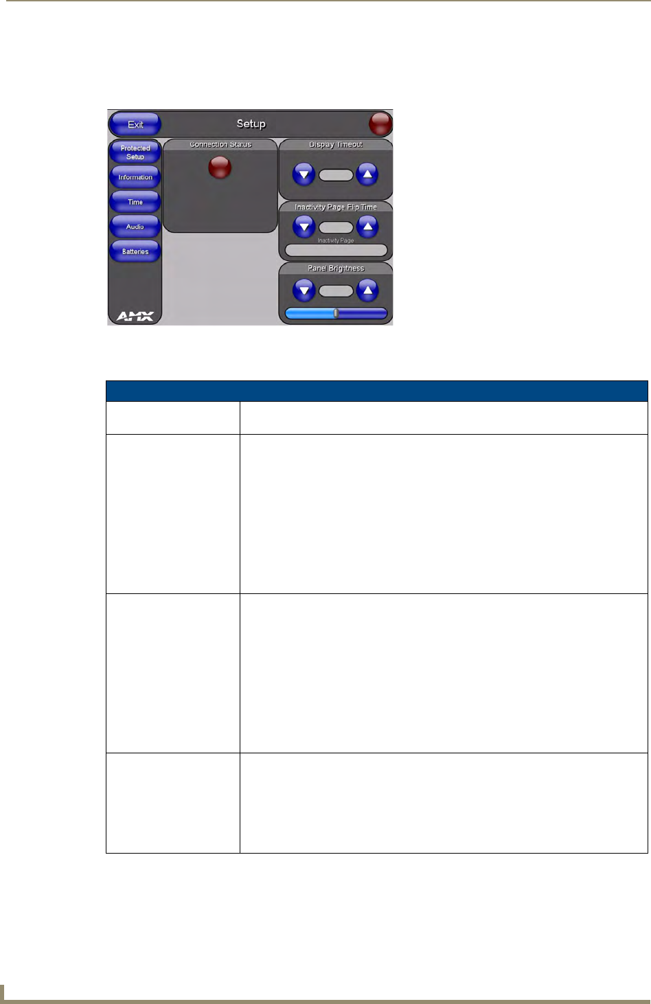
Features on this page include:
FIG. 44 MVP-8400 Setup page
Setup Page
Navigation Buttons: The buttons along on the left side of the page provide access to secondary Setup
pages (see following sections).
Connection Status icon: The icon in the upper-right corner of each Setup page shows online/offline state of
the panel to the master.
• Bright red - disconnected
• Bright green - connected. Blinks when a blink message is received to dark green
every 5 seconds for half a second then go back to bright green.
• Bright yellow - panel missed a blink message from the master. It will remain
yellow for 3 missed blink messages and then turn red. It will return to green
when a blink message is received.
Note: a Lock appears on the icon if the panel is connected to a secured NetLinx
Master.
Connection Status: Displays whether the panel is communicating externally as well as the encryption
status of the Master, the connection type (Ethernet or USB), and what System the
panel is connected to.
• Until a connection is established, the message displayed is: “Attempting via...”.
• When a connection is established, the message displayed is either: “Connected
via Ethernet “or “Connected via USB “.
• The word “Encrypted” appears when an encrypted connection is established with
a NetLinx Master.
Note: The panel must be rebooted before incorporating any panel communication
changes and to detect Ethernet connections.
Display Timeout: Indicates the length of time that the panel can remain idle before activating Sleep
mode (causing the LCD to power down).
• Press the UP/DN buttons to increase/decrease the Display Timeout setting.
Range = 0 - 240 (minutes).
• Set the timeout value to zero to disable Sleep mode.
Note: Small timeout values maximize the life of the battery charge.