
Wireless Touch Panel with Intercom Reference Guide

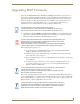
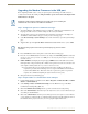
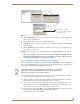
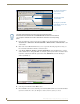
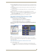
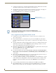
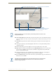

Table Of Contents
- MVP-8400iModero® ViewPoint® Wireless Touch Panel with Intercom
- MVP-8400i Modero Viewpoint Wireless Touch Panel With Intercom
- MVP-BP Power Pack
- NXA-CFSP Compact Flash
- Wireless Interface Cards
- Configuring Communications
- Modero Setup and System Settings
- Wireless Settings Page - Wireless Access Overview
- Configuring a Wireless Network Access
- Step 1: Configure the Panel’s Wireless IP Settings
- Step 2: Configure the Card’s Wireless Security Settings
- Step 3: Choose a Master Connection Mode
- Using G4 Web Control to Interact with a G4 Panel
- Using your NetLinx Master to control the G4 panel
- Upgrading MVP Firmware
- Setup Pages
- Navigation Buttons
- Setup Pages
- Information
- Protected Setup Pages
- Protected Setup Navigation Buttons
- G4 Web Control Page
- Calibration Page
- Wireless Settings Page
- Wireless Security Page
- Open (Clear Text) Settings
- Static WEP Settings
- WPA-PSK Settings
- EAP-LEAP Settings
- EAP-FAST Settings
- EAP-PEAP Settings
- EAP-TTLS Settings
- EAP-TLS Settings
- Client certificate configuration
- System Settings Page
- Other Settings
- Tools
- Programming
- Panel Calibration
- Appendix A: Text Formatting
- Appendix B - Wireless Technology
- Appendix C: Troubleshooting
- Checking AMX USBLAN device connections via Windows Device Manager
- Checking AMX USBLAN device connections via NetLinx Studio
- USB Driver
- Panel Not in Listed As a Connected Device
- Connection Status
- Panel Doesn’t Respond To Touches
- Batteries Will Not Hold Or Take A Charge
- Modero Panel Isn’t Appearing In The Online Tree Tab
- MVP Can’t Obtain a DHCP Address
- My WEP Doesn’t Seem To Be Working
- NetLinx Studio Only Detects One Of My Connected Masters
- Can’t Connect To a NetLinx Master
- Only One Modero Panel In My System Shows Up
- Panel Behaves Strangely After Downloading A Panel File Or Firmware
- Panel Fails to Charge in MVP-WDS
Upgrading MVP Firmware
48
MVP-8400i Modero Viewpoint Wireless Touch Panels
1. Complete the instructions for configuring the NetLinx Master for IP communication found in the
Upgrading the Modero Firmware via the USB port section on page 44.
2. After the panel powers-up, press and hold the two lower buttons on both sides of the display for
3 seconds to continue with the setup process and proceed to the Setup page.
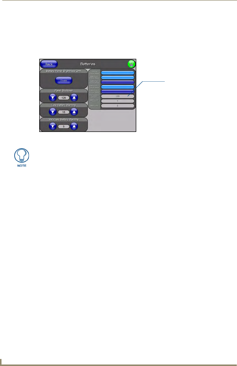
3. Press the Batteries button to open the Batteries page (FIG. 40).
Step 2: Upgrade the Docking Station firmware via USB
1. Complete the procedures outlined in the Step 1: Configure the panel for a USB Connection
Type section on page 44.
2. Prepare NetLinx Studio for communication to the panel via a Virtual Master by following the
procedures outlined in the
Step 2: Prepare Studio for communication via the USB port section on
page 44.
3. After the Communication Verification dialog window verifies active communication between the
Virtual Master and the panel, click the OnLine Tree tab in the Workspace window to view the
devices on the Virtual System. The default System value is one.
4. Right-click on the System entry and select Refresh System to re-populate the list. Verify the panel
appears in the OnLine Tree tab of the Workspace window.
The default Modero panel value is 10001.
5. Locate the latest firmware file from the www.amx.com > Tech Center > Downloadable Files >
Firmware Files > Modero Panels firmware (MVP Docking Stations: MVP-TDS/WDS) section
of the website.
6. Click on the desired Kit file link and after you’ve accepted the Licensing Agreement, verify you
have downloaded the Docking Station Kit file to a known location.
7. Select Tools > Firmware Transfers > Send to NetLinx Device from the Main menu to open the
Send to NetLinx Device dialog (
FIG. 41). Verify the panel’s System and Device number values
match those values listed within the System folder in the OnLine Tree tab of the Workspace
window.
8. Select the docking station’s Kit file (ending in VXX.kit) from the Files section (FIG. 41).
9. Enter the Device number associated with the panel and the System number associated with the
Master (listed in the OnLine Tree tab of the Workspace window). The Port field is greyed-out.
FIG. 40 Batteries page
Displays the current
docking station firmware version
The docking station firmware is shown on the right of the Batteries page.
Verify you have downloaded the latest firmware file from www.amx.com and then
save the Kit file to your computer.