
Wireless Touch Panel with Intercom Reference Guide

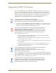
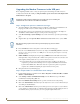
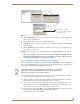
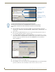
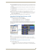
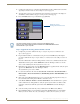
Table Of Contents
- MVP-8400iModero® ViewPoint® Wireless Touch Panel with Intercom
- MVP-8400i Modero Viewpoint Wireless Touch Panel With Intercom
- MVP-BP Power Pack
- NXA-CFSP Compact Flash
- Wireless Interface Cards
- Configuring Communications
- Modero Setup and System Settings
- Wireless Settings Page - Wireless Access Overview
- Configuring a Wireless Network Access
- Step 1: Configure the Panel’s Wireless IP Settings
- Step 2: Configure the Card’s Wireless Security Settings
- Step 3: Choose a Master Connection Mode
- Using G4 Web Control to Interact with a G4 Panel
- Using your NetLinx Master to control the G4 panel
- Upgrading MVP Firmware
- Setup Pages
- Navigation Buttons
- Setup Pages
- Information
- Protected Setup Pages
- Protected Setup Navigation Buttons
- G4 Web Control Page
- Calibration Page
- Wireless Settings Page
- Wireless Security Page
- Open (Clear Text) Settings
- Static WEP Settings
- WPA-PSK Settings
- EAP-LEAP Settings
- EAP-FAST Settings
- EAP-PEAP Settings
- EAP-TTLS Settings
- EAP-TLS Settings
- Client certificate configuration
- System Settings Page
- Other Settings
- Tools
- Programming
- Panel Calibration
- Appendix A: Text Formatting
- Appendix B - Wireless Technology
- Appendix C: Troubleshooting
- Checking AMX USBLAN device connections via Windows Device Manager
- Checking AMX USBLAN device connections via NetLinx Studio
- USB Driver
- Panel Not in Listed As a Connected Device
- Connection Status
- Panel Doesn’t Respond To Touches
- Batteries Will Not Hold Or Take A Charge
- Modero Panel Isn’t Appearing In The Online Tree Tab
- MVP Can’t Obtain a DHCP Address
- My WEP Doesn’t Seem To Be Working
- NetLinx Studio Only Detects One Of My Connected Masters
- Can’t Connect To a NetLinx Master
- Only One Modero Panel In My System Shows Up
- Panel Behaves Strangely After Downloading A Panel File Or Firmware
- Panel Fails to Charge in MVP-WDS
Upgrading MVP Firmware
45
MVP-8400i Modero Viewpoint Wireless Touch Panels
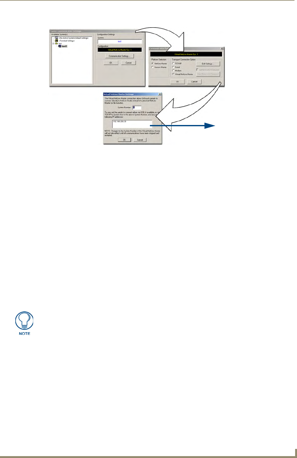
6. Click the Edit Settings button (on the Communications Settings dialog) to open the Virtual NetLinx
Master Settings dialog (
FIG. 36).
7. From within this dialog enter the System number (default is 1).
8. Click OK three times to close the open dialogs, save your settings, and return to the main NetLinx
Studio application.
9. Click the OnLine Tree tab in the Workspace window to view the devices on the Virtual System.
The default System value is one.
10. Right-click on the Empty Device Tree/System entry and select Refresh System to re-populate the
list.
The panel will not appear as a device below the virtual system number (in the Online Tree tab)
until both the system number used in step 7 for the VNM is entered into the Master Connection
section of the System Settings page and the panel is restarted.
Step 3: Confirm and Upgrade the firmware via the USB port
Use the CC-USB Type-A to Mini-B 5-wire programming cable (FG10-5965) to provide communication
between the mini-USB Program port on the touch panel and the PC. This method of communication is
used to transfer firmware Kit files and TPD4 touch panel files.
1. Verify this direct USB connection (Type-A on the panel to mini-USB on the panel) is configured
properly using the steps outlined in the previous two sections.
2. With the panel already configured for USB communication and the Virtual Master setup within
NetLinx Studio, its now time to verify the panel is ready to receive files.
3. After the Communication Verification dialog window verifies active communication between the
Virtual Master and the panel, click the OnLine Tree tab in the Workspace window (
FIG. 37) to
view the devices on the Virtual System. The default System value is one.
4. Right-click on the System entry (FIG. 37) and select Refresh System to re-populate the list. Verify
the panel appears in the OnLine Tree tab of the Workspace window.
The default Modero panel value is 10001.
FIG. 36 Assigning Communication Settings for a Virtual Master
IP Address of computer
(not needed as this is a direct
USB connection)
A mini-USB connection is only detected after it is installed onto an active panel.
Connection to a previously powered panel which then reboots, allows the PC to
detect the panel and assign an appropriate USB driver.