
Wireless Touch Panel with Intercom Reference Guide
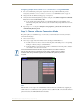
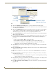

Table Of Contents
- MVP-8400iModero® ViewPoint® Wireless Touch Panel with Intercom
- MVP-8400i Modero Viewpoint Wireless Touch Panel With Intercom
- MVP-BP Power Pack
- NXA-CFSP Compact Flash
- Wireless Interface Cards
- Configuring Communications
- Modero Setup and System Settings
- Wireless Settings Page - Wireless Access Overview
- Configuring a Wireless Network Access
- Step 1: Configure the Panel’s Wireless IP Settings
- Step 2: Configure the Card’s Wireless Security Settings
- Step 3: Choose a Master Connection Mode
- Using G4 Web Control to Interact with a G4 Panel
- Using your NetLinx Master to control the G4 panel
- Upgrading MVP Firmware
- Setup Pages
- Navigation Buttons
- Setup Pages
- Information
- Protected Setup Pages
- Protected Setup Navigation Buttons
- G4 Web Control Page
- Calibration Page
- Wireless Settings Page
- Wireless Security Page
- Open (Clear Text) Settings
- Static WEP Settings
- WPA-PSK Settings
- EAP-LEAP Settings
- EAP-FAST Settings
- EAP-PEAP Settings
- EAP-TTLS Settings
- EAP-TLS Settings
- Client certificate configuration
- System Settings Page
- Other Settings
- Tools
- Programming
- Panel Calibration
- Appendix A: Text Formatting
- Appendix B - Wireless Technology
- Appendix C: Troubleshooting
- Checking AMX USBLAN device connections via Windows Device Manager
- Checking AMX USBLAN device connections via NetLinx Studio
- USB Driver
- Panel Not in Listed As a Connected Device
- Connection Status
- Panel Doesn’t Respond To Touches
- Batteries Will Not Hold Or Take A Charge
- Modero Panel Isn’t Appearing In The Online Tree Tab
- MVP Can’t Obtain a DHCP Address
- My WEP Doesn’t Seem To Be Working
- NetLinx Studio Only Detects One Of My Connected Masters
- Can’t Connect To a NetLinx Master
- Only One Modero Panel In My System Shows Up
- Panel Behaves Strangely After Downloading A Panel File Or Firmware
- Panel Fails to Charge in MVP-WDS
Configuring Communications
37
MVP-8400i Modero Viewpoint Wireless Touch Panels
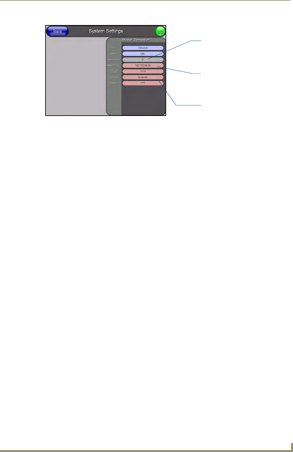
15. Press the blue Type field (from the Master Connection section) until the choice cycles to the word
Ethernet.
16. Press the Mode field until the choice cycles to the word URL.
By selecting URL, the System Number field becomes read-only (grey) because the panel pulls
this value directly from the communicating target Master (virtual or not). A Virtual Master
system value can be set within the active AMX software applications such as: NetLinx Studio,
TPD4, or IREdit.
17. Press the Master IP/URL field to open a Keyboard and enter the IP Address of the PC used as the
Virtual Master.
18. Click Done to accept the new value and return to the System Settings page.
19. Do not alter the Master Port Number value (this is the default value used by NetLinx).
20. Press the Back button to open the Protected Setup page.
21. Press the on-screen Reboot button to both save any changes and restart the panel.
FIG. 30 Sample System Settings page (for Virtual Master communication)
Enter the IP Address
information of the PC
used as a Virtual
Master
The System Number is
assigned to the Master
within the AMX
software application
(these must match)
When using a Virtual Master,
there is no need to enter a
username and/or password