
Wireless Touch Panel with Intercom Reference Guide
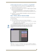
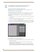
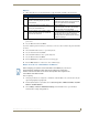
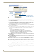
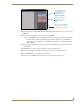
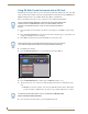

Table Of Contents
- MVP-8400iModero® ViewPoint® Wireless Touch Panel with Intercom
- MVP-8400i Modero Viewpoint Wireless Touch Panel With Intercom
- MVP-BP Power Pack
- NXA-CFSP Compact Flash
- Wireless Interface Cards
- Configuring Communications
- Modero Setup and System Settings
- Wireless Settings Page - Wireless Access Overview
- Configuring a Wireless Network Access
- Step 1: Configure the Panel’s Wireless IP Settings
- Step 2: Configure the Card’s Wireless Security Settings
- Step 3: Choose a Master Connection Mode
- Using G4 Web Control to Interact with a G4 Panel
- Using your NetLinx Master to control the G4 panel
- Upgrading MVP Firmware
- Setup Pages
- Navigation Buttons
- Setup Pages
- Information
- Protected Setup Pages
- Protected Setup Navigation Buttons
- G4 Web Control Page
- Calibration Page
- Wireless Settings Page
- Wireless Security Page
- Open (Clear Text) Settings
- Static WEP Settings
- WPA-PSK Settings
- EAP-LEAP Settings
- EAP-FAST Settings
- EAP-PEAP Settings
- EAP-TTLS Settings
- EAP-TLS Settings
- Client certificate configuration
- System Settings Page
- Other Settings
- Tools
- Programming
- Panel Calibration
- Appendix A: Text Formatting
- Appendix B - Wireless Technology
- Appendix C: Troubleshooting
- Checking AMX USBLAN device connections via Windows Device Manager
- Checking AMX USBLAN device connections via NetLinx Studio
- USB Driver
- Panel Not in Listed As a Connected Device
- Connection Status
- Panel Doesn’t Respond To Touches
- Batteries Will Not Hold Or Take A Charge
- Modero Panel Isn’t Appearing In The Online Tree Tab
- MVP Can’t Obtain a DHCP Address
- My WEP Doesn’t Seem To Be Working
- NetLinx Studio Only Detects One Of My Connected Masters
- Can’t Connect To a NetLinx Master
- Only One Modero Panel In My System Shows Up
- Panel Behaves Strangely After Downloading A Panel File Or Firmware
- Panel Fails to Charge in MVP-WDS
Configuring Communications
31
MVP-8400i Modero Viewpoint Wireless Touch Panels
Configuring multiple wireless Moderos to communicate to a target WAP200G
1. For each communicating touch panel, complete all of the steps outlined within the previous
Configuring the Modero’s wireless card for secured access to a WAP200G section on page 27.
2. Navigate back to the Wireless Settings page on each panel.
3. Verify that all communicating Modero panels are using the same SSID, encryption level, Default
Key #, and an identical Current Key value.
As an example, all panels should be set to Default Key #1 and be using aa:bb:cc..as the
Current Key string value. This same Key value and Current Key string should be used on the
target WAP.
4. Repeat steps 1 - 3 on each panel. Using the same passphrase, generates the same key for all
communicating Modero panels.
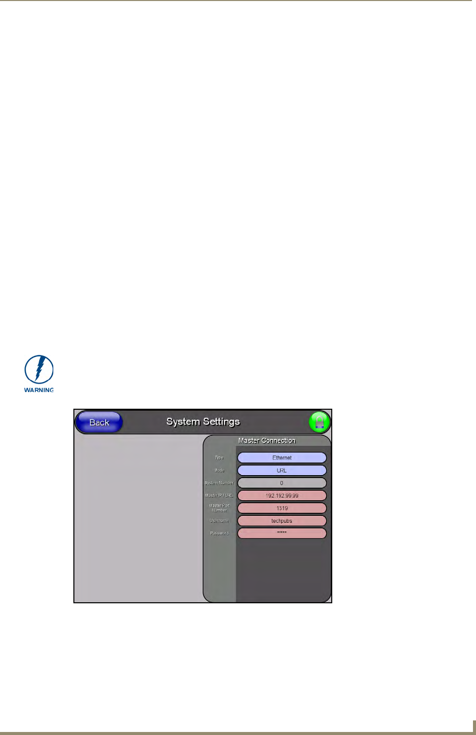
Step 3: Choose a Master Connection Mode
The panel requires you establish the type of connection you want made between it and your master.
In the Protected Setup page:
1. Select System Settings.
2. Select Type to toggle between the Master Connection Types USB and Ethernet.
A USB connection is a direct connection from the panel’s mini-USB port to a corresponding
USB port on the PC (acting as a Virtual Master).
A Wireless Ethernet connection involves indirect communication from the panel to a Master
via a wireless connection to the network.
USB
NetLinx Studio can be setup to run a Virtual Master where the PC acts as the Master by supplying its
own IP Address for communication to the panel. For a PC to establish a USB connection with a Modero
panel, it must have the AMX USBLAN driver installed.
It is recommended that firmware KIT files only be transferred over a direct connection
and only when the panel is connected to a power supply. If battery power or wireless
connection fails during a firmware upgrade, the panel flash file system may become
corrupted.
FIG. 25 System Settings page