
Wireless Touch Panel with Intercom Reference Guide
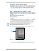
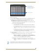
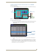
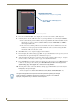
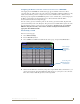
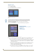
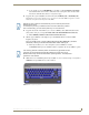
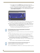
Table Of Contents
- MVP-8400iModero® ViewPoint® Wireless Touch Panel with Intercom
- MVP-8400i Modero Viewpoint Wireless Touch Panel With Intercom
- MVP-BP Power Pack
- NXA-CFSP Compact Flash
- Wireless Interface Cards
- Configuring Communications
- Modero Setup and System Settings
- Wireless Settings Page - Wireless Access Overview
- Configuring a Wireless Network Access
- Step 1: Configure the Panel’s Wireless IP Settings
- Step 2: Configure the Card’s Wireless Security Settings
- Step 3: Choose a Master Connection Mode
- Using G4 Web Control to Interact with a G4 Panel
- Using your NetLinx Master to control the G4 panel
- Upgrading MVP Firmware
- Setup Pages
- Navigation Buttons
- Setup Pages
- Information
- Protected Setup Pages
- Protected Setup Navigation Buttons
- G4 Web Control Page
- Calibration Page
- Wireless Settings Page
- Wireless Security Page
- Open (Clear Text) Settings
- Static WEP Settings
- WPA-PSK Settings
- EAP-LEAP Settings
- EAP-FAST Settings
- EAP-PEAP Settings
- EAP-TTLS Settings
- EAP-TLS Settings
- Client certificate configuration
- System Settings Page
- Other Settings
- Tools
- Programming
- Panel Calibration
- Appendix A: Text Formatting
- Appendix B - Wireless Technology
- Appendix C: Troubleshooting
- Checking AMX USBLAN device connections via Windows Device Manager
- Checking AMX USBLAN device connections via NetLinx Studio
- USB Driver
- Panel Not in Listed As a Connected Device
- Connection Status
- Panel Doesn’t Respond To Touches
- Batteries Will Not Hold Or Take A Charge
- Modero Panel Isn’t Appearing In The Online Tree Tab
- MVP Can’t Obtain a DHCP Address
- My WEP Doesn’t Seem To Be Working
- NetLinx Studio Only Detects One Of My Connected Masters
- Can’t Connect To a NetLinx Master
- Only One Modero Panel In My System Shows Up
- Panel Behaves Strangely After Downloading A Panel File Or Firmware
- Panel Fails to Charge in MVP-WDS
Configuring Communications
26
MVP-8400i Modero Viewpoint Wireless Touch Panels
4. Press the red SSID field (FIG. 19) to display an on-screen Network Name (SSID) keyboard.
5. In this keyboard, enter the SSID name used on your target Wireless Access Point (case sensitive).
The card should be given the SSID used by the target WAP. If this field is left blank, the unit
will attempt to connect to the first available WAP. By default, all WAP200Gs use AMX as
their assigned SSID value.
One of the most common problems associated with connection to a WAP arise because the
SSID was not entered properly. You must maintain the same case when entering the SSID
information. ABC is not the same as Abc.
6. Click Done when you’ve completed typing in the information.
7. From the Open (Clear Text) Settings page (FIG. 19), press the Save button to incorporate your new
information into the panel and begin the communication process.
8. Verify the fields in the IP Settings section have been properly configured. Refer to Step 1: Configure
the Panel’s Wireless IP Settings section on page 21 for detailed information.
9. Press the Back button to return to the Protected Setup page and press the on-screen Reboot button
to both save any changes and restart the panel. Remember that you will need to navigate to the
System Settings page and configure the connection to a target Master.
10. After the panel restarts, return to the Wireless Settings page’s RF Link Info section and verify the
Link Quality and Signal Strength:
The descriptions are: None, Poor, Fair, Good, Ve r y G o o d, and Excellent (FIG. 17).
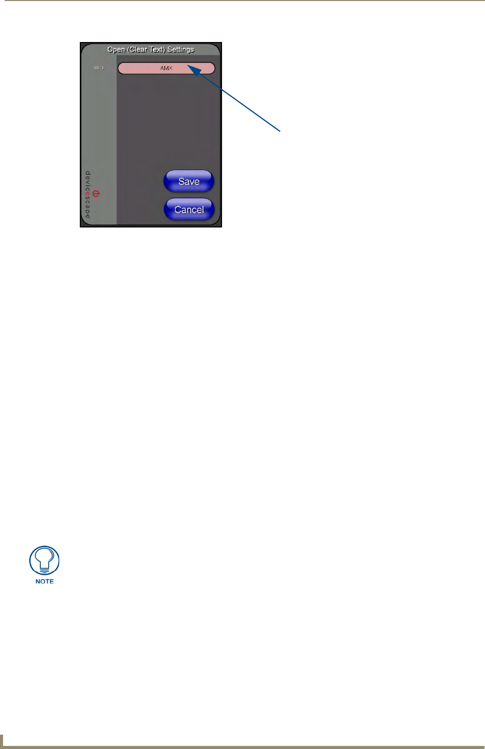
FIG. 19 Wireless Settings page - Open (Clear Text) security method
Required Information:
- SSID (Network Name used by the Target WAP)
By default, this field displays the
SSID - AMX
The signal strength field should provide some descriptive text regarding the strength
of the connection to a Wireless Access Point. If there is no signal or no IP Address
displayed; configuration of your network could be required.