
Wireless Touch Panel with Intercom Reference Guide
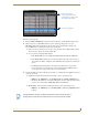
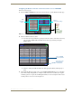
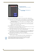
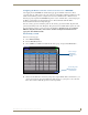
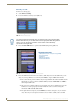
Table Of Contents
- MVP-8400iModero® ViewPoint® Wireless Touch Panel with Intercom
- MVP-8400i Modero Viewpoint Wireless Touch Panel With Intercom
- MVP-BP Power Pack
- NXA-CFSP Compact Flash
- Wireless Interface Cards
- Configuring Communications
- Modero Setup and System Settings
- Wireless Settings Page - Wireless Access Overview
- Configuring a Wireless Network Access
- Step 1: Configure the Panel’s Wireless IP Settings
- Step 2: Configure the Card’s Wireless Security Settings
- Step 3: Choose a Master Connection Mode
- Using G4 Web Control to Interact with a G4 Panel
- Using your NetLinx Master to control the G4 panel
- Upgrading MVP Firmware
- Setup Pages
- Navigation Buttons
- Setup Pages
- Information
- Protected Setup Pages
- Protected Setup Navigation Buttons
- G4 Web Control Page
- Calibration Page
- Wireless Settings Page
- Wireless Security Page
- Open (Clear Text) Settings
- Static WEP Settings
- WPA-PSK Settings
- EAP-LEAP Settings
- EAP-FAST Settings
- EAP-PEAP Settings
- EAP-TTLS Settings
- EAP-TLS Settings
- Client certificate configuration
- System Settings Page
- Other Settings
- Tools
- Programming
- Panel Calibration
- Appendix A: Text Formatting
- Appendix B - Wireless Technology
- Appendix C: Troubleshooting
- Checking AMX USBLAN device connections via Windows Device Manager
- Checking AMX USBLAN device connections via NetLinx Studio
- USB Driver
- Panel Not in Listed As a Connected Device
- Connection Status
- Panel Doesn’t Respond To Touches
- Batteries Will Not Hold Or Take A Charge
- Modero Panel Isn’t Appearing In The Online Tree Tab
- MVP Can’t Obtain a DHCP Address
- My WEP Doesn’t Seem To Be Working
- NetLinx Studio Only Detects One Of My Connected Masters
- Can’t Connect To a NetLinx Master
- Only One Modero Panel In My System Shows Up
- Panel Behaves Strangely After Downloading A Panel File Or Firmware
- Panel Fails to Charge in MVP-WDS
Configuring Communications
23
MVP-8400i Modero Viewpoint Wireless Touch Panels
In the Protected Setup page:
1. Press the Wireless Settings button (located on the lower-left) to open the Wireless Settings page.
2. Navigate to the Access Point MAC Address section of this page and press the on-screen
Site Survey button. This action launches the Site Survey page which displays a listing of all
detected WAPs in the communication range of the internal card.
The card scans its environment every four seconds and adds any new WAPs found to the list.
Every scan cycle updates the signal strength field.
Access points are tracked by MAC Address.
If the WAP’s SSID is set as a blank, then N/A is displayed within the SSID field.
If the WAP’s SSID is hidden (not broadcast) it will not show up on the site survey
screen but it can still be configured via the SSID field on the specified security mode
screen.
If a WAP is displayed in the list is not detected for 10 scans in a row it is then
removed from the screen. In this way, a user can walk around a building and see
access points come and go as they move in and out of range.
3. Sort the information provided on this page by pressing on a column name and toggling the direction
of the adjacent arrow.
Up arrow - indicates that the information is being sorted in a Ascending order.
SSID (A to Z), Channel (1 to 14), Security (Unknown to WEP), Signal (None to
Excellent). The firmware considers the following to be the security order from least
secure to most secure: Open, WEP, WPA, WPA2, and Unknown.
Down arrow - indicates that the information is being sorted in a Descending order.
SSID (Z to A), Channel (11 to 6), Security (WEP to Unknown), Signal (Excellent
to None)
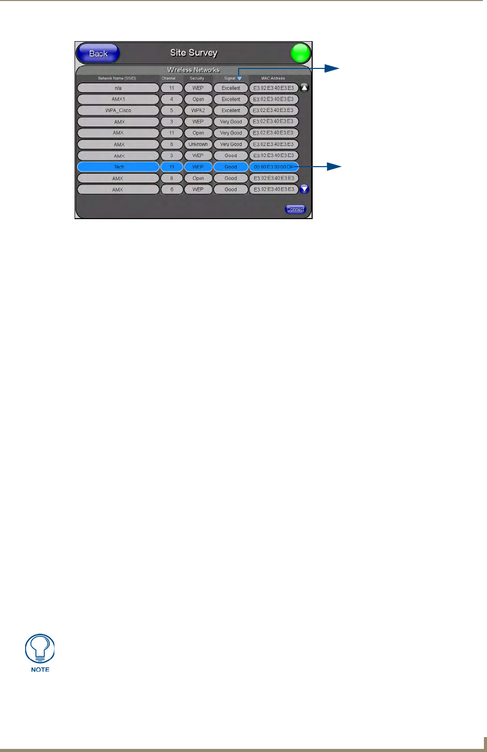
FIG. 16 Site Survey page
Indicates a selected AP
Indicates the currently
active column and the order
in which the data is being sorted -
(Descending order shown)
If the panel detects more than 10 WAPs, the Up/Down arrows at the far right side of
the page become active (blue) and allow the user to scroll through the list of entries.