
Wireless Touch Panel with Intercom Reference Guide
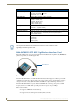
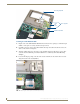

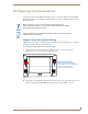
Table Of Contents
- MVP-8400iModero® ViewPoint® Wireless Touch Panel with Intercom
- MVP-8400i Modero Viewpoint Wireless Touch Panel With Intercom
- MVP-BP Power Pack
- NXA-CFSP Compact Flash
- Wireless Interface Cards
- Configuring Communications
- Modero Setup and System Settings
- Wireless Settings Page - Wireless Access Overview
- Configuring a Wireless Network Access
- Step 1: Configure the Panel’s Wireless IP Settings
- Step 2: Configure the Card’s Wireless Security Settings
- Step 3: Choose a Master Connection Mode
- Using G4 Web Control to Interact with a G4 Panel
- Using your NetLinx Master to control the G4 panel
- Upgrading MVP Firmware
- Setup Pages
- Navigation Buttons
- Setup Pages
- Information
- Protected Setup Pages
- Protected Setup Navigation Buttons
- G4 Web Control Page
- Calibration Page
- Wireless Settings Page
- Wireless Security Page
- Open (Clear Text) Settings
- Static WEP Settings
- WPA-PSK Settings
- EAP-LEAP Settings
- EAP-FAST Settings
- EAP-PEAP Settings
- EAP-TTLS Settings
- EAP-TLS Settings
- Client certificate configuration
- System Settings Page
- Other Settings
- Tools
- Programming
- Panel Calibration
- Appendix A: Text Formatting
- Appendix B - Wireless Technology
- Appendix C: Troubleshooting
- Checking AMX USBLAN device connections via Windows Device Manager
- Checking AMX USBLAN device connections via NetLinx Studio
- USB Driver
- Panel Not in Listed As a Connected Device
- Connection Status
- Panel Doesn’t Respond To Touches
- Batteries Will Not Hold Or Take A Charge
- Modero Panel Isn’t Appearing In The Online Tree Tab
- MVP Can’t Obtain a DHCP Address
- My WEP Doesn’t Seem To Be Working
- NetLinx Studio Only Detects One Of My Connected Masters
- Can’t Connect To a NetLinx Master
- Only One Modero Panel In My System Shows Up
- Panel Behaves Strangely After Downloading A Panel File Or Firmware
- Panel Fails to Charge in MVP-WDS
Wireless Interface Cards
17
MVP-7500/8400 Modero Viewpoint Wireless Touch Panels
5. Grip the antenna by its sides and carefully peel-off the remaining protective film on the double-
sided tape.
6. Align the antenna into the long vertical groove in the cutout and firmly adhere it to the inner surface
of the housing. Make sure the wire is threaded along the left side of the cutout, this helps in the
removal of the cutout.
7. With the antenna now securely attached to the MVP’s inner housing, remove the cutout by carefully
pulling up on the cutout and threading the antenna wire through the
T-shaped opening.
Closing and Securing the MVP Enclosure
Once the card has been installed, close and re-secure the outer housing:
1. Reinstall the dark grey trim along the top rim of the board (A in FIG. 12).
2. While angling the top rim of the MVP’s rear outer housing (B in FIG. 12) down toward the IR
Emitters, insert the four outer housing latches into their corresponding attachment locations along
the top rim of the MVP panel (two on either side of the IR Emitters).
3. While firmly holding the top rims together, gently press down on the bottom ridge of the outer
housing (at the latch locations) and verify that each housing latch fits within its corresponding
attachment location on the board. When done, complete the insertion of the remaining housing
latches.
4. Verify that the notches along the bottom of the plastic battery slot separator strip also fit into the
three provided alignment holes on the circuit board.
5. Firmly press down around the entire rim of the outer housing to snap the cover back into place.
6. Use a grounded Phillips-head screwdriver to insert and resecure the two housing screws removed in
Step 1.
7. Insert any available batteries back into the battery compartment.
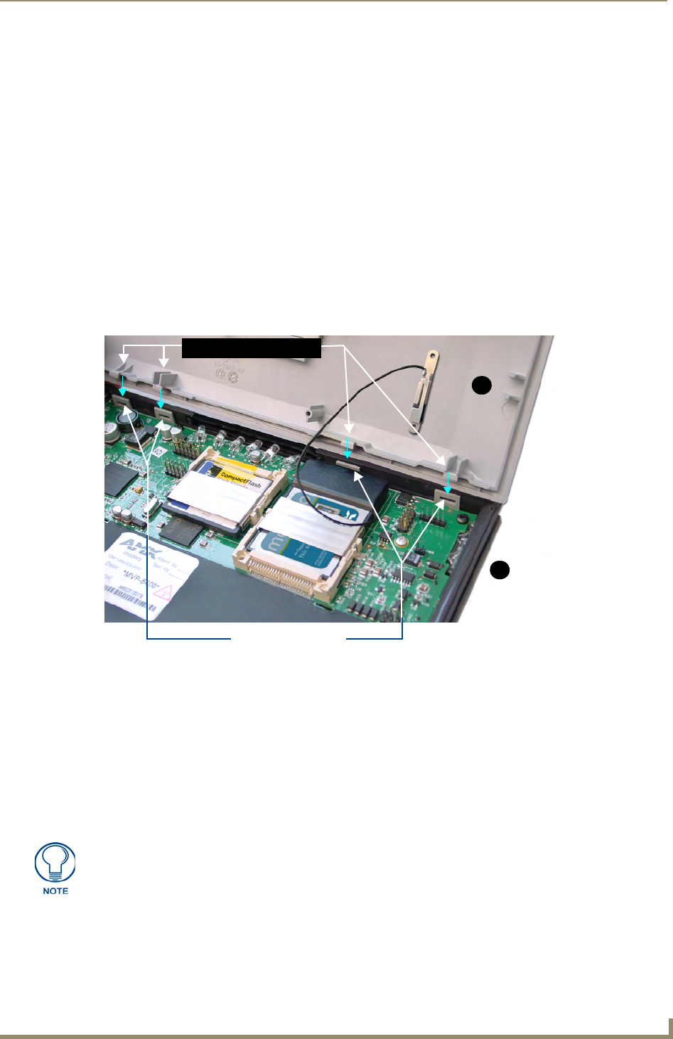
FIG. 12 Outer housing latch attachment locations
4 Outer housing latch
attachment locations
B
A
Outer housing latches (4)
Be careful not to pinch the antenna wire in the housing.