
Wireless Touch Panel with Intercom Reference Guide
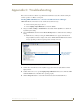
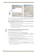
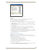
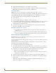
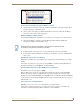


Table Of Contents
- MVP-8400iModero® ViewPoint® Wireless Touch Panel with Intercom
- MVP-8400i Modero Viewpoint Wireless Touch Panel With Intercom
- MVP-BP Power Pack
- NXA-CFSP Compact Flash
- Wireless Interface Cards
- Configuring Communications
- Modero Setup and System Settings
- Wireless Settings Page - Wireless Access Overview
- Configuring a Wireless Network Access
- Step 1: Configure the Panel’s Wireless IP Settings
- Step 2: Configure the Card’s Wireless Security Settings
- Step 3: Choose a Master Connection Mode
- Using G4 Web Control to Interact with a G4 Panel
- Using your NetLinx Master to control the G4 panel
- Upgrading MVP Firmware
- Setup Pages
- Navigation Buttons
- Setup Pages
- Information
- Protected Setup Pages
- Protected Setup Navigation Buttons
- G4 Web Control Page
- Calibration Page
- Wireless Settings Page
- Wireless Security Page
- Open (Clear Text) Settings
- Static WEP Settings
- WPA-PSK Settings
- EAP-LEAP Settings
- EAP-FAST Settings
- EAP-PEAP Settings
- EAP-TTLS Settings
- EAP-TLS Settings
- Client certificate configuration
- System Settings Page
- Other Settings
- Tools
- Programming
- Panel Calibration
- Appendix A: Text Formatting
- Appendix B - Wireless Technology
- Appendix C: Troubleshooting
- Checking AMX USBLAN device connections via Windows Device Manager
- Checking AMX USBLAN device connections via NetLinx Studio
- USB Driver
- Panel Not in Listed As a Connected Device
- Connection Status
- Panel Doesn’t Respond To Touches
- Batteries Will Not Hold Or Take A Charge
- Modero Panel Isn’t Appearing In The Online Tree Tab
- MVP Can’t Obtain a DHCP Address
- My WEP Doesn’t Seem To Be Working
- NetLinx Studio Only Detects One Of My Connected Masters
- Can’t Connect To a NetLinx Master
- Only One Modero Panel In My System Shows Up
- Panel Behaves Strangely After Downloading A Panel File Or Firmware
- Panel Fails to Charge in MVP-WDS

Appendix C: Troubleshooting
182
MVP-8400i Modero Viewpoint Wireless Touch Panels
6. Plug-in the mini-USB cable into the corresponding port on the panel.
7. Wait a few seconds and refresh the system. This re-establishes communication with the Virtual
Master. The panel should now appear in the list of available devices.
Connection Status
Symptom: My Connection Status button isn’t blinking and it says the USB is connecting.
"USB Connecting" is displayed when the panel is trying to establish USB communication with the PC
(either within the NetLinx Studio or TPDesign4 applications) but not establishing the connection.
1. Remove the USB connector from the panel and close any AMX applications.
2. Reboot the panel.
3. Launch the AMX application and attempt to reconnect to the panel.
4. If using Studio for Virtual Master communication, establish a Virtual Master connection, verify the
correct System number, stop communication with the Virtual Master, and then re-establish
communication by refreshing the system.
5. After the first page appears, re-connect the mini-USB connector to the panel and confirm the
appearance of the USB icon in the System Tray.
Panel Doesn’t Respond To Touches
Verify that the protective laminate coating on the LCD is removed before beginning any
calibration process.
The protective cover acts to press on the entire LCD and makes calibration difficult because
the user can’t calibrate on specific crosshairs when the sheet is pressing on the whole LCD.
Batteries Will Not Hold Or Take A Charge
Symptom: Batteries will not hold or take a charge and there is no indication of charging, on the
bargraphs or in the Batteries Setup page.
To keep the batteries from being damaged (from operating at too low a level), the firmware places them
into a protected state.
The panel must have the latest firmware (if it doesn’t, the firmware can be found at amx.com, in the
Dealers/Tech Center > Firmware Files.> Modero).
1. Load the firmware into the panel, using NetLinx Studio.
2. After loading the firmware, power cycle the MVP (this is a complete power cycle, not a Reboot).
The panel will now show the current firmware version within the Setup > Panel Information page.
3. Connect the power supply to the panel. You will see 2 warning messages on the display.
The first one warns that the batteries are low and must be charged.
The second warning tells you that the second battery is in aprotected mode, and needs to be
inserted into the first battery slot.
4. Swap the batteries, the top slot is considered the first slot, and now the batteries will be reset.
5. Wait a few minutes and then check the Batteries page on the MVP to see any charging activity on
the bar graphs.
The "Sensor" device (in the Online Tree tab below the MVP panel)should show v1.24 or
higher after the upgrade, as shown in
FIG. 85: