
Wireless Touch Panel with Intercom Reference Guide
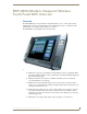
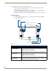
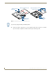
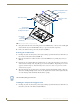
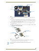

Table Of Contents
- MVP-8400iModero® ViewPoint® Wireless Touch Panel with Intercom
- MVP-8400i Modero Viewpoint Wireless Touch Panel With Intercom
- MVP-BP Power Pack
- NXA-CFSP Compact Flash
- Wireless Interface Cards
- Configuring Communications
- Modero Setup and System Settings
- Wireless Settings Page - Wireless Access Overview
- Configuring a Wireless Network Access
- Step 1: Configure the Panel’s Wireless IP Settings
- Step 2: Configure the Card’s Wireless Security Settings
- Step 3: Choose a Master Connection Mode
- Using G4 Web Control to Interact with a G4 Panel
- Using your NetLinx Master to control the G4 panel
- Upgrading MVP Firmware
- Setup Pages
- Navigation Buttons
- Setup Pages
- Information
- Protected Setup Pages
- Protected Setup Navigation Buttons
- G4 Web Control Page
- Calibration Page
- Wireless Settings Page
- Wireless Security Page
- Open (Clear Text) Settings
- Static WEP Settings
- WPA-PSK Settings
- EAP-LEAP Settings
- EAP-FAST Settings
- EAP-PEAP Settings
- EAP-TTLS Settings
- EAP-TLS Settings
- Client certificate configuration
- System Settings Page
- Other Settings
- Tools
- Programming
- Panel Calibration
- Appendix A: Text Formatting
- Appendix B - Wireless Technology
- Appendix C: Troubleshooting
- Checking AMX USBLAN device connections via Windows Device Manager
- Checking AMX USBLAN device connections via NetLinx Studio
- USB Driver
- Panel Not in Listed As a Connected Device
- Connection Status
- Panel Doesn’t Respond To Touches
- Batteries Will Not Hold Or Take A Charge
- Modero Panel Isn’t Appearing In The Online Tree Tab
- MVP Can’t Obtain a DHCP Address
- My WEP Doesn’t Seem To Be Working
- NetLinx Studio Only Detects One Of My Connected Masters
- Can’t Connect To a NetLinx Master
- Only One Modero Panel In My System Shows Up
- Panel Behaves Strangely After Downloading A Panel File Or Firmware
- Panel Fails to Charge in MVP-WDS
NXA-CFSP Compact Flash
9
MVP-8400i Modero Viewpoint Wireless Touch Panels
2. Place the circuit board on a flat level surface so that the IR Emitters are pointing away from you
(
FIG. 6).
3. Insert the tip of a grounded flat-head screwdriver into one of the card removal grooves (located on
either side of the existing Compact Flash card), and gently pry it out of the slot (
FIG. 7). Repeat this
process on the opposite card removal groove. This alternating action causes the pre-existing card to
"wiggle" away from the on-board connector pins.
4. Slip your finger into the opening (between the connector pins and the card resulting from step 3)
and push the card out.
5. Finish the process by firmly gripping the exposed sides of the card and pulling it out (FIG. 7). USE
CARE WHEN HANDLING THE CARD.
6. Insert the new card firmly into the slot opening connector (FIG. 7) until the contact pins are
completely inside the card and securely attached to the pin sockets.
FIG. 6 Location and orientation of the Compact Flash cards (both MVP panels)
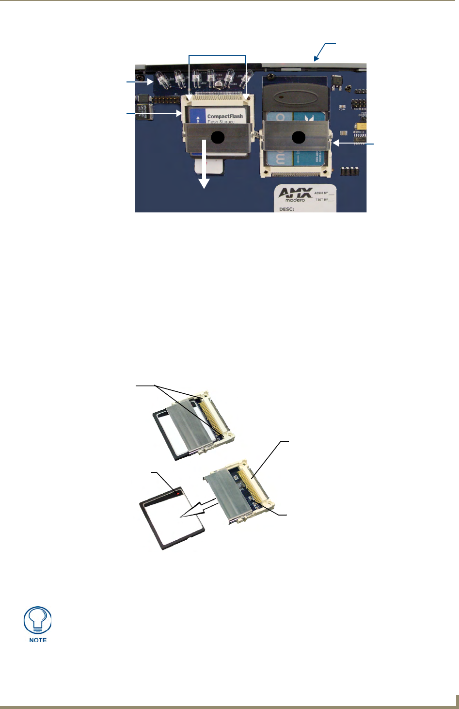
FIG. 7 Removing/installing a Compact Flash Memory card
Compact Flash
Card removal grooves
IR Emitters
Internal circuit board
(top view - detail)
A B
Wireless Interface
card
card
Card removal
grooves
Insert with arrow
facing towards the pins
On-board Compact
Flash connector (with pins)
Connector opening
Any new Compact Flash card upgrade is detected by the panel only after the unit
cycles power.