
Wireless Touch Panel with Intercom Reference Guide

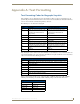
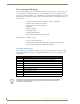
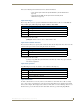
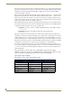
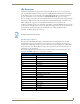


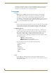
Table Of Contents
- MVP-8400iModero® ViewPoint® Wireless Touch Panel with Intercom
- MVP-8400i Modero Viewpoint Wireless Touch Panel With Intercom
- MVP-BP Power Pack
- NXA-CFSP Compact Flash
- Wireless Interface Cards
- Configuring Communications
- Modero Setup and System Settings
- Wireless Settings Page - Wireless Access Overview
- Configuring a Wireless Network Access
- Step 1: Configure the Panel’s Wireless IP Settings
- Step 2: Configure the Card’s Wireless Security Settings
- Step 3: Choose a Master Connection Mode
- Using G4 Web Control to Interact with a G4 Panel
- Using your NetLinx Master to control the G4 panel
- Upgrading MVP Firmware
- Setup Pages
- Navigation Buttons
- Setup Pages
- Information
- Protected Setup Pages
- Protected Setup Navigation Buttons
- G4 Web Control Page
- Calibration Page
- Wireless Settings Page
- Wireless Security Page
- Open (Clear Text) Settings
- Static WEP Settings
- WPA-PSK Settings
- EAP-LEAP Settings
- EAP-FAST Settings
- EAP-PEAP Settings
- EAP-TTLS Settings
- EAP-TLS Settings
- Client certificate configuration
- System Settings Page
- Other Settings
- Tools
- Programming
- Panel Calibration
- Appendix A: Text Formatting
- Appendix B - Wireless Technology
- Appendix C: Troubleshooting
- Checking AMX USBLAN device connections via Windows Device Manager
- Checking AMX USBLAN device connections via NetLinx Studio
- USB Driver
- Panel Not in Listed As a Connected Device
- Connection Status
- Panel Doesn’t Respond To Touches
- Batteries Will Not Hold Or Take A Charge
- Modero Panel Isn’t Appearing In The Online Tree Tab
- MVP Can’t Obtain a DHCP Address
- My WEP Doesn’t Seem To Be Working
- NetLinx Studio Only Detects One Of My Connected Masters
- Can’t Connect To a NetLinx Master
- Only One Modero Panel In My System Shows Up
- Panel Behaves Strangely After Downloading A Panel File Or Firmware
- Panel Fails to Charge in MVP-WDS
Appendix A: Text Formatting
165
MVP-8400i Modero Viewpoint Wireless Touch Panels
Refer to the following Send Commands for more detailed information:
Input mask ranges
These ranges allow a user to specify the minimum and maximum numeric value for a field. Only one
range is allowed per field. Using a range implies a numeric entry ONLY.
An example from the above table:
[0|255] This allows a user to enter a value from 0 to 255.
Input mask next field characters
These characters allow you to specify a list of characters that cause the keyboard to move the focus to the
next field when pressed instead of inserting the text into the text area.
An example from the above table:
{.} or {:} or {.:} Tells the system that after a user hits any of these keys, proceed to the
next text area input box.
Input mask operations
Input Mask Operators change the behavior of the field in the following way:
Input mask literals
To define a literal character, enter any character, other than those shown in the above table (including
spaces, and symbols). A back-slash ('\') causes the character that follows it to be displayed as the literal
character. For example, \A is displayed just as the letter A. To define one of the following characters as a
literal character, precede that character with a back-slash. Text entry operation using Input Masks.
• ^BIM - Sets the input mask for the specified addresses. (see the ^BIM section on
page 115).
• ^BMF subcommand %MK - sets the input mask of a text area (see the
^BMF section on page 117).
Input Mask Ranges
Character Meaning
[ Start range
] End range
| Range Separator
Input Mask Next Field Char
Character Meaning
{ Start Next Field List
} End Next Field List
Input Mask Operators
Character Meaning
< Forces all characters to be converted to lowercase
> Forces all characters to be converted to uppercase
^ Sets the overflow flag for this field