
Wireless Touch Panel with Intercom Reference Guide
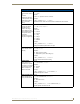
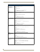
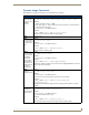

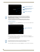
Table Of Contents
- MVP-8400iModero® ViewPoint® Wireless Touch Panel with Intercom
- MVP-8400i Modero Viewpoint Wireless Touch Panel With Intercom
- MVP-BP Power Pack
- NXA-CFSP Compact Flash
- Wireless Interface Cards
- Configuring Communications
- Modero Setup and System Settings
- Wireless Settings Page - Wireless Access Overview
- Configuring a Wireless Network Access
- Step 1: Configure the Panel’s Wireless IP Settings
- Step 2: Configure the Card’s Wireless Security Settings
- Step 3: Choose a Master Connection Mode
- Using G4 Web Control to Interact with a G4 Panel
- Using your NetLinx Master to control the G4 panel
- Upgrading MVP Firmware
- Setup Pages
- Navigation Buttons
- Setup Pages
- Information
- Protected Setup Pages
- Protected Setup Navigation Buttons
- G4 Web Control Page
- Calibration Page
- Wireless Settings Page
- Wireless Security Page
- Open (Clear Text) Settings
- Static WEP Settings
- WPA-PSK Settings
- EAP-LEAP Settings
- EAP-FAST Settings
- EAP-PEAP Settings
- EAP-TTLS Settings
- EAP-TLS Settings
- Client certificate configuration
- System Settings Page
- Other Settings
- Tools
- Programming
- Panel Calibration
- Appendix A: Text Formatting
- Appendix B - Wireless Technology
- Appendix C: Troubleshooting
- Checking AMX USBLAN device connections via Windows Device Manager
- Checking AMX USBLAN device connections via NetLinx Studio
- USB Driver
- Panel Not in Listed As a Connected Device
- Connection Status
- Panel Doesn’t Respond To Touches
- Batteries Will Not Hold Or Take A Charge
- Modero Panel Isn’t Appearing In The Online Tree Tab
- MVP Can’t Obtain a DHCP Address
- My WEP Doesn’t Seem To Be Working
- NetLinx Studio Only Detects One Of My Connected Masters
- Can’t Connect To a NetLinx Master
- Only One Modero Panel In My System Shows Up
- Panel Behaves Strangely After Downloading A Panel File Or Firmware
- Panel Fails to Charge in MVP-WDS
Panel Calibration
160
MVP-8400i Modero Viewpoint Wireless Touch Panels
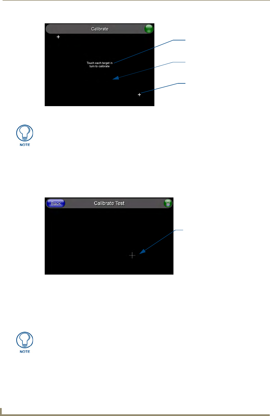
Testing your Calibration
1. Press and hold down the on-screen Calibration button for 6 seconds to enter the Calibration Test
page (
FIG. 78).
2. Press anywhere on this page to confirm the on-screen crosshairs match your touch points.
3. If the crosshairs do not appear directly below your LCD touch points, press the Back button and
recalibrate the panel using the above steps.
Peel the protective plastic film from the LCD.
4. Exit this Calibration Test page by pressing the Back button to return to the Protected Setup page.
FIG. 77 Touch Panel Calibration Screens
The request to touch the crosshairs
is the first on-screen message
Calibration successful is the second
on-screen message that appears
On-screen crosshairs used for
calibration of the touch device
after the calibration process is
completed
If the calibration was improperly set and you cannot return to the Calibration
page (through the panel’s firmware); you can then access this firmware page via
G4 WebControl where you can navigate to the Protected Setup page and press the
Calibrate button through your VNC window.
This action causes the panel to go to the Calibration page seen above, where you
can physically recalibrate the actual touch panel again using the above procedures.
FIG. 78 Calibration Test page
On-screen crosshairs is used to
verify a proper calibration of the
panel
If the protective plastic film on the LCD is not removed, the panel may not respond
properly to touch points on the LCD nor allow proper screen calibration.