
Wireless Touch Panel with Intercom Reference Guide
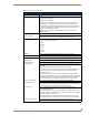
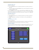
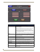
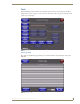
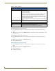
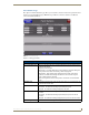
Table Of Contents
- MVP-8400iModero® ViewPoint® Wireless Touch Panel with Intercom
- MVP-8400i Modero Viewpoint Wireless Touch Panel With Intercom
- MVP-BP Power Pack
- NXA-CFSP Compact Flash
- Wireless Interface Cards
- Configuring Communications
- Modero Setup and System Settings
- Wireless Settings Page - Wireless Access Overview
- Configuring a Wireless Network Access
- Step 1: Configure the Panel’s Wireless IP Settings
- Step 2: Configure the Card’s Wireless Security Settings
- Step 3: Choose a Master Connection Mode
- Using G4 Web Control to Interact with a G4 Panel
- Using your NetLinx Master to control the G4 panel
- Upgrading MVP Firmware
- Setup Pages
- Navigation Buttons
- Setup Pages
- Information
- Protected Setup Pages
- Protected Setup Navigation Buttons
- G4 Web Control Page
- Calibration Page
- Wireless Settings Page
- Wireless Security Page
- Open (Clear Text) Settings
- Static WEP Settings
- WPA-PSK Settings
- EAP-LEAP Settings
- EAP-FAST Settings
- EAP-PEAP Settings
- EAP-TTLS Settings
- EAP-TLS Settings
- Client certificate configuration
- System Settings Page
- Other Settings
- Tools
- Programming
- Panel Calibration
- Appendix A: Text Formatting
- Appendix B - Wireless Technology
- Appendix C: Troubleshooting
- Checking AMX USBLAN device connections via Windows Device Manager
- Checking AMX USBLAN device connections via NetLinx Studio
- USB Driver
- Panel Not in Listed As a Connected Device
- Connection Status
- Panel Doesn’t Respond To Touches
- Batteries Will Not Hold Or Take A Charge
- Modero Panel Isn’t Appearing In The Online Tree Tab
- MVP Can’t Obtain a DHCP Address
- My WEP Doesn’t Seem To Be Working
- NetLinx Studio Only Detects One Of My Connected Masters
- Can’t Connect To a NetLinx Master
- Only One Modero Panel In My System Shows Up
- Panel Behaves Strangely After Downloading A Panel File Or Firmware
- Panel Fails to Charge in MVP-WDS
Setup Pages
99
MVP-8400i Modero Viewpoint Wireless Touch Panels
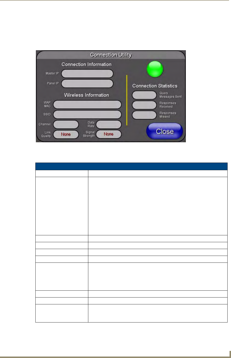
Connection Utility Page
The options on the Connection Utility page allow you to utilize your panel as a site survey tool. While in
this page, move around your wireless network coverage area and see if there are any weak points within
the spaces between your WAPs (
FIG. 69).
Features on this page include:
FIG. 74 Connection Utility page
Connection Utility Page
Close: Closes the Connection Utility popup.
Connection Status icon: The icon in the upper-right corner of the utility provides a constant visual i
indication of current connection status.
A message is sent to the master once per second and expects a response.
• If it is received the button stays green.
• If it is missed the button goes yellow.
• After three misses (3 seconds) it will go red until a response from the master
is received, and then it will be green again.
Once per second, a user can know whether they are standing in a good
wireless area (all green), an area of limited coverage (lots of yellow, some
green, some red), or an area with no coverage (all red).
Connection Information
Master IP The IP Address for the connected master.
Panel IP The IP Address for the panel.
Wireless Information
WAP MAC The MAC Address for the WAP currently in use.
If the MAC Address changes, it means the panel has switched/roamed to a
different access point. This can be used to determine coverage for each access
point and help isolate "brown" areas where coverage is minimal or non-existent,
and thus require another access installed.
SSID Displays the currently used SSID of the target WAP.
Channel The RF channel being used for connection to the WAP (read -only).
Data Rate The data rate (in Mbps) at which the panel is currently communicating with the
target WAP.
Note: Data rates for 802.11b communication are: 1, 2, 5.5, and 11 Mbps.