Operation/Reference Guide MVP-5100/5150 Modero® Viewpoint Widescreen Touch Panels Mio Modero Touch Panels Last Updated: 12/2/2008
AMX Limited Warranty and Disclaimer All products returned to AMX require a Return Material Authorization (RMA) number. The RMA number is obtained from the AMX RMA Department. The RMA number must be clearly marked on the outside of each box. The RMA is valid for a 30-day period. After the 30-day period the RMA will be cancelled. Any shipments received not consistent with the RMA, or after the RMA is cancelled, will be refused. AMX is not responsible for products returned without a valid RMA number.
FCC Information This device complies with Part 15 of the FCC Rules and Industry Canada RSS 210, subject to the following two conditions: (1) this device may not cause harmful interference, and (2) this device must accept any interference received; including interference that may cause undesired operation. Federal Communications Commission (FCC) Statement This equipment has been tested and found to comply with the limits for a Class B digital device, pursuant to Part 15 of the FCC rules.
Software License and Warranty Agreement • LICENSE GRANT. AMX grants to Licensee the non-exclusive right to use the AMX Software in the manner described in this License. The AMX Software is licensed, not sold. This license does not grant Licensee the right to create derivative works of the AMX Software. The AMX Software consists of generally available programming and development software, product documentation, sample applications, tools and utilities, and miscellaneous technical information.
Table of Contents Table of Contents Introduction ........................................................................................................1 MVP-5150 5.2" Modero ViewPoint WiFi Touch Panel .............................................. 2 MVP-5100 5.2" Modero ViewPoint IR Touch Panel .................................................. 4 Memory ....................................................................................................................
Table of Contents Automatically setting SSID ............................................................................................ 29 Manually setting SSID.................................................................................................... 29 Configuring multiple wireless touch panels to communicate to a target WAP.............. 32 Step 3: Choose a Master Connection Mode ........................................................... 33 Panel downloads and firmware updates .............
Table of Contents Upgrading Firmware ........................................................................................85 Upgrading the Modero Firmware via the USB port ................................................ 85 Step 1: Configure the panel for a USB Connection Type .............................................. 85 Step 2: Prepare Studio for communication via the USB port ........................................ 86 Step 3: Confirm and Upgrade the firmware via the USB port ....................
Table of Contents Input mask output examples ....................................................................................... 154 URL Resources ...................................................................................................... 155 Special escape sequences ........................................................................................... 155 Appendix B: Wireless Technology ..................................................................
Introduction Introduction The MVP-5100 Modero® Viewpoint® IR Touch Panel (FG5966-08) and the MVP-5150 Modero® Viewpoint® WiFi Touch Panel (FG5966-07) are wireless ergonomic devices, with all control established through a NetLinx Master or through an IR receiver. Both utilize a 5.2" Color Active LCD to display a 800 x 480 pixel image with 262,144 colors. The MVP-5150 uses both a pre-installed 802.11g WPA/ WPA2 SDIO wireless card and standard IR communication, and the MVP-5100 uses only IR for communication.
Introduction MVP-5150 5.2" Modero ViewPoint WiFi Touch Panel MVP-5150 Specifications (FG5966-07) Dimensions: 4 3/4" x 7 9/16" x 13/16" (120.7 mm x 191.8 mm x 20.3 mm) Weight: • 1.25 lbs (0.57 kg) Enclosure: Matte black plastic. Power Requirements (Without Charging): Panel with battery fully charged: • Constant current draw: 0.3 A @ 12 VDC • Startup current draw: 0.4 A @ 12 VDC Power Requirements (While Charging): Panel while charging battery: • Constant current draw: 1.
Introduction MVP-5150 Specifications (FG5966-07) (Cont.) External Components Connector: 5-pin Mini-USB connector used for output to USB programming, firmware update, and touch panel file transfer between the PC and the target panel. Note: When connecting the panel to PC using a CC-USB (or compatible) cable, be sure to power the panel On before attempting to connect the USB cable from the PC to the mini-USB port on the panel. DC power port: 2.5 mm port to power the panel away from a Charging Station.
Introduction MVP-5100 5.2" Modero ViewPoint IR Touch Panel The MVP-5100 differs from the MVP-5150 in that it does not have a built-in wireless card or the capacity to install one, and only communicates with other devices via IR. Otherwise, the two devices are identical. MVP-5100 Specifications (FG5966-08) Dimensions: 4 3/4" x 7 9/16" x 13/16" (120.7 mm x 191.8 mm x 20.3 mm) Weight: • 1.25 lbs (0.57 kg) Enclosure: Matte black plastic.
Introduction MVP-5100 Specifications (FG5966-08) (Cont.) External Components (Cont.) DC power port: 2.5 mm port to power the panel away from a Charging Station. Speaker: • 4 Ohm • 2 Watts 300Hz cutoff frequency • NOTE: Speaker is only used for feedback beeps, and will not transmit standard audio. IR Emitters: Transmit IR over 20 feet (6.10 m) from the panel. • IR emitters on G4 panels share the device address number of the panel.
Introduction Transferring firmware KIT files over a direct USB connection should only be done when the panel is connected to a power supply. If battery power fails during a firmware upgrade, the panel flash file system may become corrupted. Basic Operation The MVP-5100 and MVP-5150 are operated using their integral touchscreens. If the device has shut down, a touch of the touchscreen will reactivate it.
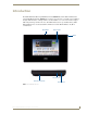
Accessories Accessories Table Charging Station The MVP-5100 and MVP-5150 may be used with the MVP-TCS-52 Table Charging Station (FG59661X) (FIG. 4), which acts both as a charging station and a direct power connection. The charging station is available in either white (FG5966-10) or black (FG5966-11). FIG. 4 MVP-TCS-52-GB Table Charging Station - Front MVP-TCS-52 Specifications Dimensions (HWD): • 8.0” x 4.75” x 3.5” (20.32cm x 12.07cm x 8.89cm) Weight: • .65 lbs (.
Accessories Powering the MVP-TCS-52 The MVP-TCS-52 uses a PS3.0 power supply (included with the touch panel or available separately from www.amx.com) to provide direct power for the MVP panel both for standard functions and for charging its internal battery. 1. Connect the terminal end of the PS3.0 power supply to the PWR connector on the bottom of the MVP-TCS-52. 2.
Accessories Wall Charging Station The optional MVP-WCS-52 Wall Charging Station (FG5966-1X) offers the same recharging and connection features as the Table Charging Station, with the advantage of being placed within accessible locations where the table station is either inconvenient or impractical (FIG. 6). The Wall Charging Station is available in either white (FG5966-13) or black (FG5966-12). MVP-WCS-52 MVP-5100 Security Release button FIG.
Accessories MVP-WCS-52 Specifications Front Panel Components: • Securing Magnets: Prevent MVP touch panel from falling free during ejection. • Security Latch: Adds the primary layer of security when mounting an MVP touch panel. When the device is inserted, this latch grabs onto the rear of the touch panel and secures it to prevent it from being removed. • Interface Connector Pins: A set of retractable pins (male) that connect to the underside MVP connector strip.
Accessories Recharging To recharge the touch panel: 1. Slide the device into the Wall Charging Station cradle bottom-first and make sure the device is fully seated in the Charging Station. 2. Press the top of the touch panel back until it clicks. The touch panel is now locked into the Charging Station, and the station will automatically charge the device’s battery. (Please refer to the Battery Settings Page section on page 53 to check on the battery charge status.) 3.
Accessories Installing the MVP-WCS-52 Since the Wall Charging Station is intended to be affixed to a wall or other permanent structure, care must be taken to ensure its proper installation to prevent potential damage to any touch panel placed within. Other than wall installation tools, the only tool required for this installation is a #1 Phillips screwdriver.
Accessories To assist with wiring, and to avoid mechanical stresses on the wire and the mechanism of the Wall-Mounted Charging Station, the top right knockout is preferred for use. 3. Run the power cable through the knockout into the box. Pull out about six inches (15.25cm) of cable into the box to facilitate installation of the MVP-WCS-52. 4. Slide the plastic back box into the hole, being careful not to twist or pinch the cable, and set it flush with the wall (FIG. 8).
Accessories Strip 0.25 inch (6.35 mm) of wire insulation off all wires. Insert each wire into the appropriate opening on the connector. Turn the screws clockwise to secure the wires in the connector. Do not over-torque the screws; doing so can bend the seating pins and damage the connector. 7. Secure the power cable to the device, using either of the two tie-wrap anchors included in the Installation Kit at the top rear of the device (FIG. 9).
Accessories Screw holes Plastic back box Neodymium magnets MVP-WCS-52 Rubber feet FIG. 10 Installation of MVP-WCS-52 For ease of installation, put each screw on a neodymium magnet in the device’s interior compartment to keep them on hand until they are needed. 11. After fully seating the screws, wipe down the area around the screw holes with the alcohol prep pad from the Installation Kit. Take a rubber foot and remove its adhesive backing.
Accessories Installing the Optional Metal Rough-In Box The optional Metal Rough-In Box (FG037-11) is 10 inches (25.40cm) wide at its widest dimension (wider than the bezel of the Wall Charging Station), and is only intended for pre construction installations (FIG. 11). The Metal Rough-In Box is used in conjunction with the Wall Charging Station’s plastic back box. The Metal Rough-In Box must be located behind 3/8" (0.95cm) to 3/4" (1.91cm) of wall/mounting surface material.
Accessories Other MVP-WCS-52 installations The Wall-Mounted Charging Station is designed to be installed in various different locations, such as into the face of a wooden podium or the top of a table. Depending upon the ability to wire it to a power source, Wall-Mounted Charging Stations may be installed on vertical or horizontal surfaces composed of such materials as wood, brick, and glass.
Accessories 18 MVP-5100/5150 Modero Viewpoint Touch Panels
Configuring Communication Configuring Communication All control for a MVP-5150 touch panel is established through a NetLinx Master. Communication between the MVP and the Master consists of using either Wireless Ethernet (DHCP, Static IP) or USB. References to Ethernet in this manual focus on the use of Wireless Ethernet via the MVP-5150’s WiFi Card. Configuration for a MVP-5100 touch panel is made through the mini-USB port, as it does not have a WiFi Card.
Configuring Communication IR Communication Both the MVP-5100 and MVP-5150 may be used as infrared remote devices for other AMX controllers or third-party devices. The devices can transmit IR over 20 feet (6.10 m) from the panel at frequencies of 38KHz and 455KHz, as well as up to eight user-programmed frequencies between 20KHz and 1.5MHz. IR receivers and transmitters on G4 panels share the device address number of the panel. Both devices include an IR transmitter for communication between devices.
Configuring Communication Modero Setup and System Settings All AMX Modero panels, including the MVP-5100 and MVP-5150, feature on-board Setup pages. Use the options in the Setup pages to access panel information and make various configuration changes. Accessing the Setup and Protected Setup Pages 1. At any time, use the device’s stylus to press down and hold the reset button on the left side of the device for 3-5 seconds.
Configuring Communication The default password for the Protected Setup page is 1988, but this may be changed at any time. For more information on the Setup and Protected Setup pages, refer to the Setup Pages section on page 45 and the Protected Setup Pages section on page 55. Setting the Panel’s Device Number In the Protected Setup page: 1. Press the Device Number field in the Device ID section to open the Device Number keypad. 2.
Configuring Communication Wireless Settings - Wireless Access Overview (MVP-5150 Only) DHCP When choosing DHCP, a DHCP server must be accessible before the fields are populated. If the SSID (Network Name) and WEP fields have not previously been configured, the Wireless Settings page will not work until the panel is rebooted. The parameters of the wireless card must be set before selecting Ethernet as the Master Connection Type.
Configuring Communication Wireless communication using a DHCP Address In the Protected Setup page: 1. Select Wireless Settings. Wireless communication is set within the IP Settings section of this page (FIG. 15). Wireless Access Point Site Survey Button FIG. 15 Wireless Settings page (IP Settings section) 2. Toggle the DHCP/Static field from the IP Settings section until the choice cycles to DHCP. This action causes all fields in the IP Settings section, other than Host Name, to be greyed-out.
Configuring Communication Wireless communication using a Static IP Address 1. From the Protected Setup page, press the Wireless Settings button to open the Wireless Settings page. Wireless communication is set within the IP Settings section of this page (FIG. 15). Check with your System Administrator for a pre-reserved Static IP Address to be assigned to the panel. This address must be obtained before continuing with the Static assignment of the panel. 2.
Configuring Communication Using the Site Survey tool This tool allows a user to "sniff out" all transmitting Wireless Access Points within the detection range of the internal wireless card (FIG. 16).
Configuring Communication If the panel detects more than 10 WAPs, the Up/Down arrows at the far right side of the page become active (blue) and allow the user to scroll through the list of entries. 4. Select a desired Access Point by touching the corresponding row. The up arrow and down arrow will be grayed out if ten or fewer access points are detected. If more are detected, then they will be enabled as appropriate so that the user can scroll through the list. 5.
Configuring Communication Wireless card security settings MVP connection IP info FIG. 17 Wireless Settings page (showing a sample unsecured configuration) Select an OPEN (unsecured) WAP Connecting to the WAP begins the communication. FIG. 18 Site Survey of available WAPS (Unsecured WAP shown selected) Required information: - SSID (Network Name used by the Target WAP) By default, this field displays the SSID - AMX FIG. 19 Wireless Settings page - Open (Clear Text) security method 5.
Configuring Communication 6. Click Done when complete. 7. From the Open (Clear Text) Settings page (FIG. 19), press the Save button to incorporate the new information into the device and begin the communication process. 8. Verify the proper configuration in the fields in the IP Settings section. Refer to Step 1: Configure the Device’s Wireless IP Settings (MVP-5150 Only) section on page 23 for detailed information. 9.
Configuring Communication 2. Locate the Wireless Security menu (FIG. 21). FIG. 21 Wireless Security page 3. Press the Static WEP button to open the Static WEP Settings dialog (FIG. 22). Requ ired In formation: - SSI D (Net work Name used by t he Target WAP) Encryption Method Passphrase WE P Key assignment Authentication Met hod FIG. 22 Wireless Settings page - Static WEP security method 4. Press the SSID field.
Configuring Communication 6. Toggle the Default Key field to choose a WEP Key value (from 1- 4) that matches what will be used on the target. This value MUST MATCH on both devices. These WEP Key identifier values must match for both devices. 7. Press the particular WEP Keys button to launch the WEP Passphrase keyboard. 8. Within the WEP Passphrase keyboard (FIG. 23), enter a character string or word (such as AMXPanel) and press Done when finished. FIG.
Configuring Communication 12. Verify that the fields within the IP Settings section have been properly configured. Refer to Step 1: Configure the Device’s Wireless IP Settings (MVP-5150 Only) section on page 23 for detailed information. 13. Press the Back button to navigate to the Protected Setup page and press the on-screen Reboot button to save any changes and restart the panel. Remember that you will need to navigate to the System Settings page and configure the connection to a target Master. 14.
Configuring Communication Step 3: Choose a Master Connection Mode Since the MVP-5150 may connect with a Master via USB or Ethernet, this requires a decision on the type of connection to be made between it and the Master. The MVP-5100 may only use USB for connection. To establish a Master connection: 1. From the Protected Setup page, select System Settings. 2. Select Type to toggle between the Master Connection Types USB and Ethernet (FIG. 25).
Configuring Communication Panel downloads and firmware updates The MVP-5100 and MVP-5150 devices support a USB driver for panel downloads and firmware updates. This means that the devices connect to a host computer for updates through their Mini USB ports (FIG. 26). All touch panel setup is done through NetLinx Studio and TPDesign4. Mini-USB Port FIG. 26 USB Port on the MVP-5100/5150 Firmware downloads require use of the USB Programming Cable (FG10-5965) and a computer running Windows XP.
Configuring Communication 6. In the new window: - Select Use the following IP Address. Under IP address, provide an IP address. Ensure that it is in the same subnet as the IP address given to the usb0 interface on the MVP-5100, but make sure that it has a different node number. The IP address cannot be the same as the panel`s USB IP address. Under Subnet mask, set the suitable subnet mask. Click OK. 7. In the next box (FIG. 28), make sure to: Select Search for the best driver in these locations.
Configuring Communication 9. The Windows XP machine now searches for the suitable driver (FIG. 29). FIG. 29 Found New Hardware Wizard while searching for the driver 10. Once the system finds the driver, it displays its choice (FIG. 30). Click Finish to complete the driver installation. FIG. 30 Completing the Found New Hardware Wizard The USB interface will require a static IP address. Proceed to the next steps to set up the IP address on the USB interface. In Windows XP: 1.
Configuring Communication 3. Right click on the selected device and select Properties to open the Local Area Connection Properties window (FIG. 31). FIG. 31 Local Area Connection Properties 4. In the Local Area Connection Properties window (FIG. 31) under the General tab, select Internet Protocol (TCP/IP) and click on Properties to open the Internet Protocol (TCP/IP) Properties window. (FIG. 32) FIG. 32 Internet Protocol (TCP/IP) Properties 5. In the new window: Select Use the following IP Address.
Configuring Communication Systems Settings page of the Protected Settings menu, as shown in FIG. 33. (For more information, refer to the Protected Setup Pages section on page 55.) IP Address FIG. 33 IP address location on the System Settings Page Under Subnet mask, set the subnet mask to 255.255.255.0. Do not enter the Gateway or DNS information. Click on OK. Do not set USB to the same subnet address as the Ethernet card. 6. In the Local Area Connection Properties window, click on OK.
Configuring Communication 2. In NetLinx Studio, select Settings > Master Communication Settings from the Main menu to open the Master Communication Settings dialog (FIG. 34). FIG. 34 Master Communications Settings dialog box 3. Click the Communications Settings button to open the Communications Settings dialog (FIG. 35). FIG. 35 Communications Settings dialog box 4. Click the NetLinx Master radio button in the Platform Selection section. 5.
Configuring Communication 6. Click the Edit Settings button to open the Virtual NetLinx Master Settings dialog (FIG. 36). FIG. 36 Virtual NetLinx Master Settings dialog box 7. Select the IP Address for the AMX USB device in the Available Connections section. The IP address will appear in the Current Connection field. Click OK to save the settings and close the window. 8. In the Communications Settings dialog box, the IP address for the Virtual NetLinx Master will appear in the display field.
Configuring Communication 3. Set the Master Port and select Done. 4. If you enabled password security on your Master, set the username and password within the device. 5. Select the blank field Username to open the keyboard. 6. Set the Username and select Done. 7. Select the blank field Password to open the keyboard. 8. Set the Password and select Done. 9. Press the Back button to return to the Protected Setup page. 10. Press the Reboot button to reboot the device and confirm changes.
Configuring Communication FIG. 38 Communications Settings dialog box 8. Click OK to close the open dialogs, save the settings, and return to the main NetLinx Studio application. 9. Place the panel in the Table Charging Station or in the Wall Charging Station. 10. After the panel powers up, press and hold down the reset button for 3 seconds to continue with the setup process and proceed to the Setup page. 11. Select Protected Setup > System Settings to open the System Settings page (FIG. 39).
Configuring Communication 18. Press the on-screen Reboot button to save any changes and restart the panel. The panel will now be connected to the master. 19. Click the OnLine Tree tab in the Workspace window to view the devices on the Virtual System. The default System value is one. 20. Right-click on the Empty Device Tree/System entry and select Refresh System to re-populate the list.
Configuring Communication 44 MVP-5100/5150 Modero Viewpoint Touch Panels
Setup Pages Setup Pages Both the MVP-5100 and MVP-5150 feature on-board Setup pages. Use the options in the Setup pages to access panel information and make various configuration changes. To access the Setup pages, press the reset button and hold for 3 to 5 seconds (FIG. 40). Reset button: Press and hold for 3 seconds to access the Setup pages. FIG. 40 Setup Page Access buttons Setup Pages The Setup page (FIG. 41) allows quick access to several essential panel properties: FIG.
Setup Pages Setup Page (Cont.) Connection Status: Displays whether the panel has external communication, as well as the encryption status of the Master, the connection type (Ethernet or USB), and to which System the panel is connected. • Until a connection is established, the message displayed is: “Attempting via Ethernet” or "Attempting via USB". • When a connection is established, the message displayed is either: “Connected via Ethernet “or “Connected via USB “.
Setup Pages Navigation Buttons The following Navigation buttons (FIG. 42) appear on the left side of the Setup page: Press to access the Protected Setup pages. Press to access the Project Information page in order to view information on the TPDesign file being used, and Panel Information page in order to view panel specific information such as resolution and memory. Press to access the Time page in order to alter the time and date settings on the Master.
Setup Pages Information Button The Information button allows access of both the Project Information page, which contains data on the TPDesign4 file being used with the MVP-5100, and the Panel Information page, which contains detailed information on the panel itself. To access these pages: 1. Press and hold the Information button until the Project Information button and the Panel Information button slide from the left.
Setup Pages Project Information Page (Cont.) Sales Order: Displays the sales order information. Purchase Order: Displays the purchase order information. AMX IR 38K Assigned Port: Displays the AMX 38 kHz IR channel port used by the IR Emitter on the panel. • This information is specified in TPD4 (Project Properties > IR Emitters & Receivers tab).
Setup Pages Panel Information Page The Panel Information page provides detailed panel information (FIG. 44). FIG. 44 Panel Information page Features on this page include: Panel Information Page Back: Saves all changes and returns to the previous page. Connection Status icon: The icon in the upper-right corner of each Setup page provides a constant visual indication of current connection status. Note: a Lock appears on the icon if the panel is connected to a secured NetLinx Master.
Setup Pages Time & Date Settings Page The options on the Time & Date Settings page (FIG. 45) allows setting and adjusting of time and date information on the NetLinx Master. If the time and/or date on the Master is modified, all connected devices will be updated to reflect the new information. FIG. 45 Time and Date Setup page Both touch panels do not have an on-board clock, so the only way to modify a panel’s time without altering the Master is via NetLinx Code.
Setup Pages Audio Settings Page The Audio Settings page allows adjustment of volume levels and panel sounds settings (FIG. 46). FIG. 46 Audio Settings pages Features on these pages include: Audio Settings Page Back: Saves all changes and returns to the previous page. Connection Status icon: The icon in the upper-right corner of each Setup page provides a constant visual indication of current connection status. Note: a Lock appears on the icon if the panel is connected to a secured NetLinx Master.
Setup Pages Battery Settings Page The options on the Battery Settings page allow setting of power warning preferences and battery status information, and adjustment of the display times for battery warnings (FIG. 47). FIG. 47 Battery page Features on this page include: Battery Page Back: Saves all changes and returns to the previous page. Connection Status icon: The icon in the upper-right corner of each Setup page provides a constant visual indication of current connection status.
Setup Pages 54 MVP-5100/5150 Modero Viewpoint Touch Panels
Protected Setup Pages Protected Setup Pages The Protected Setup page (FIG. 48) provides secured access to advanced panel configuration options, including communication and security settings. The Protected Setup page is accessed through the Setup page (please refer to the Setup Pages section on page 45). To access the Protected Setup pages: 1. Press the reset button and hold for 3 to 5 seconds to access the Setup pages. 2. Select the Protected Setup button on the left side of the screen. 3.
Protected Setup Pages Protected Setup Page (Cont.) System Recovery: • Reset System Settings - Deletes all of the current configuration parameters on the panel (including IP Addresses, Device Number assignments, Passwords, and other presets). This option invokes a Confirmation dialog, prompting you to confirm your selection before resetting the panel. • Remove User Pages - Removes all TPD4 touch panel pages currently on the panel, including the pre-installed AMX Demo pages.
Protected Setup Pages The Protected Setup page for the MVP-5100 is slightly different, as some of the functions are disabled (FIG. 50). The particular functions that are disabled are explained in detail in the Protected Setup Navigation Buttons section on page 58. FIG. 50 Protected Setup page for the MVP-5100 Rebooting and shutting down the touch panel To reboot either the MVP-5100 or the MVP-5150: 1. Access the Protected Setup page. 2. Press the Reboot button. 3.
Protected Setup Pages Protected Setup Navigation Buttons The Protected Setup Navigation Buttons (FIG. 51) appear on the left edge of the Protected Setup page. The Navigation Buttons for the MVP-5100 have different functionality than those for the MVP-5150, as shown below. Press to access the System Settings page, which contains IP Settings and Master Connection information. Press to access the Wireless Settings page, which allows configuration of wireless connection settings. (Disabled in the MVP-5100.
Protected Setup Pages System Settings Page The System Settings page (FIG. 53) displays sets the NetLinx Master’s communication settings. FIG. 53 System Settings page The elements of this page include: System Settings Page Elements Back: Saves all changes and returns to the previous page. Connection Status icon: The icon in the upper-right corner of each Protected Setup page provides a constant visual indication of current connection status.
Protected Setup Pages System Setting Page Elements (Cont.) Mode Cycles between the connection modes: URL, Listen, NDP(UDP,) URL(UDP), and Auto. (Ethernet Only - disabled when USB is selected) • URL - In this mode, enter the IP/URL, Master Port Number, and username/ password (if used) on the Master. The System Number field is read-only - the panel obtains this information from the Master.
Protected Setup Pages Wireless Settings Page (MVP-5150 Only) Use the options on the Wireless Settings page (FIG. 54) to configure communication settings for the wireless CF card (802.11b/g), and read the device number assigned to the panel. Since the MVP-5100 does not have wireless capability, the button to this page is greyed out in the MVP-5100 Protected Settings page. FIG.
Protected Setup Pages Wireless Settings Page (Cont.) IP Settings (Cont.) Secondary DNS Enter the secondary DNS address for this panel. Domain Enter a unique name to the panel for DNS look-up. MAC Address This unique address identifies the wireless Ethernet card in the panel (readonly). Active Roaming on Channels 1, 6, and 11 When enabled, connection allows active roaming between WAPs by switching between channels 1, 6, and 11 if the other channel is unavailable.
Protected Setup Pages Wireless Settings Page (Cont.) Wireless Security (Cont.): EAP-TTLS This button opens the EAP-TTLS Settings page (FIG. 64 on page 76). “EAP-TTLS” security is designed for wireless environments where having a Radius server directly validate the identity of the client (panel) is necessary before allowing it access to the network. • Refer to the EAP-TTLS Settings section on page 76 for further details.
Protected Setup Pages Wireless Security The options on the Wireless Security section (FIG. 55) include the wireless security methods supported by the NXA-WC80211GCF Wi-Fi card. These security methods incorporate WPA, WPA2, and EAP technology, some of which require the upload of unique certificate files to a target panel. Refer to the Appendix B: Wireless Technology section on page 156 for further information. Some encryption and security features may or may not be supported: Wireless Security Support 802.
Protected Setup Pages Open (Clear Text) Settings Press the Open (Clear Text) button to open the Open (Clear Text) Settings page (FIG. 56). FIG. 56 Wireless Settings page - Open (Clear Text) Settings Open security does not utilize any encryption methodology, but requires an SSID (alpha-numeric) entry. This entry must match the Network Name (SSID) entry of the target WAP so the panel knows what device it is using to communicate with the network.
Protected Setup Pages Static WEP Settings Press the Static WEP button to open the Static WEP Settings page (FIG. 57). FIG. 57 Wireless Settings page - Static WEP Settings Static WEP security requires that both a target WAP be identified and an encryption method be implemented prior to establishing communication. In addition to providing both Open and Shared Authentication capabilities, this page also supports Hexadecimal and ASCII keys.
Protected Setup Pages Static WEP Settings (Cont.) WEP Keys: This feature provides another level of security by selecting up to four WEP Keys. Push any of the four buttons to open an on-screen keyboard. Both ASCII and HEX keys are supported. Up to four keys can be configured for both. • An ASCII key utilizes either 5 or 13 ASCII characters • A HEX key utilizes either 10 or 26 Hexidecimal characters Press Done to accept any changes and save the new value.
Protected Setup Pages FIG. 58 Wireless Settings page - WPA-PSK Settings Enter a pass phrase with a minimum of 8 characters and a maximum of 63. The exact same pass phrase (including capitalization) must be entered in the access point. WPA-PSK Settings SSID (Service Set Identifier): Opens an on-screen keyboard to enter the SSID name used on the target WAP. The SSID is a unique name used by the WAP, and is assigned to all panels on that network.
Protected Setup Pages All three of these certificate-using security methods are documented in the following sections. EAP Authentication goes a step beyond simply encrypting data transfers, but also requires that a set of credentials be validated before the client (panel) is allowed to connect to the rest of the network (FIG. 59). Please note that no user intervention is necessary during this process, as it proceeds automatically based on the configuration parameters entered into the panel. LAN 802.
Protected Setup Pages EAP-LEAP Settings Press the EAP-LEAP button to open the EAP-LEAP Settings page (FIG. 60). FIG. 60 Wireless Settings page - EAP-LEAP Settings EAP (Extensible Authentication Protocol) is an Enterprise authentication protocol that can be used in both wired and wireless network environments. EAP requires the use of an 802.1x Authentication Server, also known as a Radius server. The configuration fields described below take variable length strings as inputs.
Protected Setup Pages EAP-LEAP Settings SSID (Service Set Identifier): Opens an on-screen keyboard to enter the SSID name used on the target WAP. The SSID is a unique name used by the WAP, and is assigned to all panels on that network. An SSID is required by the WAP before the panel is permitted to join the network. • The SSID is case sensitive and must not exceed 32 characters. • Make sure this setting is the same for all points in the wireless network. • NXA-WAP250Gs use AMX as their default SSID.
Protected Setup Pages EAP-FAST Settings Press the EAP-FAST button to open the EAP-FAST Settings dialog (FIG. 62). FIG. 62 Wireless Settings page - EAP-FAST Settings EAP-FAST (Flexible Authentication via Secure Tunneling) security was designed for wireless environments where security and ease of setup are equally desirable. EAP-FAST uses a certificate file, however it can be configured to download the certificate automatically the first time the panel attempts to authenticate itself.
Protected Setup Pages EAP-FAST Settings (Cont.) Anonymous Identity: Opens an on-screen keyboard to enter an IT provided alphanumeric string which (similar to the username) is used as the identity, but that does not represent a real user. This information is used as a fictitious name which might be seen by sniffer programs during the initial connection and setup process between the panel and the Radius server. In this way the real identity (username) is protected.
Protected Setup Pages EAP-PEAP Settings Press the EAP-PEAP button to open the EAP-PEAP Settings page (FIG. 63). FIG. 63 Wireless Settings page - EAP-PEAP Settings PEAP (Protected Extensible Authentication Protocol) was developed as a way to securely transmit authentication information, such as passwords, over a wireless network environment. PEAP uses only server-side public key certificates and therefore does not need a client (panel) certificate which makes the configuration and setup easier.
Protected Setup Pages EAP-PEAP security is designed for wireless environments where it is necessary to transmit data securely over a wireless network. EAP-PEAP Settings SSID (Service Set Identifier): Opens an on-screen keyboard to enter the SSID name used on the target WAP. The SSID is a unique name used by the WAP, and is assigned to all panels on that network. An SSID is required by the WAP before the panel is permitted to join the network. • The SSID is case sensitive and must not exceed 32 characters.
Protected Setup Pages EAP-TTLS Settings Press the EAP-TTLS button to open the EAP-TTLS Settings page (FIG. 64). FIG. 64 Wireless Settings page - EAP-TTLS Settings TTLS (EAP Tunneled Transport Layer Security) is an authentication method that does not use a client certificate to authenticate the panel. However. this method is more secure than PEAP because it does not broadcast the identity of the user.
Protected Setup Pages EAP-TTLS Settings (Cont.) Identity: Opens an on-screen keyboard. Enter an EAP Identity string (used by the panel to identify itself to an Authentication (RADIUS) Server). Note: This information is similar to a username used to login to a secured server or workstation. This works in tandem with the Password string which is similar to the password entered to gain access to a secured workstation. Typically, this is in the form of a username such as: jdoe@amx.com.
Protected Setup Pages EAP-TLS Settings Press the EAP-TLS button to open the EAP-TLS Settings page (FIG. 65). FIG. 65 Wireless Settings page - EAP-TLS Settings TLS (Transport Layer Security) was the original standard wireless LAN EAP authentication protocol. TLS requires additional work during the deployment phase, but provides additional security since even a compromised password is not enough to break into an EAP-TLS protected wireless network environment.
Protected Setup Pages EAP-TLS Settings (Cont.) Certificate Authority: When pressed, the panel displays an on-screen Certificate Authority (CA) File Location keyboard, for entering the name of the certificate authority file which is used to validate the server certificate. This field is optional. If a server certificate is used, it should first be downloaded into the panel and the Certificate Authority field should then be set to the name of that certificate file.
Protected Setup Pages Client certificate configuration A client certificate can be configured by an IT department in several ways. The client certificate and private key can both be incorporated into one file or split into two separate files. In addition, the file format used by these files could be PEM, DER, or PKCS12. These formats are described later in this section. The following table describes how to fill in the fields for each possible case.
Protected Setup Pages Calibration Page The Calibration page (FIG. 66) allows you to calibrate the touch panel for accurate button selection. FIG. 66 Calibration page 1. Press and hold the reset button for 6 seconds to access the Calibration page (see FIG. 48). 2. Press the crosshairs in turn. If the crosshairs are not touched within ten seconds, the MVP-5100 will return to the Protected Setup page. 3. The page will read "Calibration Successful. Touch to continue.
Protected Setup Pages Other Settings Press the Other Settings button to display the two settings options for Cache and Password. Press one of the options within three seconds, or the two options buttons will slide back behind the Other Settings button. Cache Settings Page The options on the Cache Settings page (FIG. 67) allow setting and clearing of the flash memory cache, as well as viewing the status of the current cache settings.
Protected Setup Pages Password Settings Page The options on the Password Settings page (FIG. 68) allow assignment of passwords required for users to access the Protected Setup page, and to release the device from a MVP-WCS-52 Charging Station. FIG. 68 Password Setup page Features on this page include: Password Setup Page Back: Saves all changes and returns to the previous page.
Protected Setup Pages The User Access section allows the Administrator to control access of all individuals using or attempting to use the MVP-5100. From this section, new users may be given access rights to the device; however, they will NOT be given access to the Protected Settings page. Only one of the main passwords may be used to access the Protected Settings page. An individual user password may not be used to access the Protected Settings page unless it matches one of the main passwords.
Upgrading Firmware Upgrading Firmware The MVP-5100 and MVP-5150 come already loaded with on-board firmware, which is upgradeable through the use of the latest version of NetLinx Studio. Refer to the NetLinx Studio version 2.x or higher Instruction Manual for more information on how to download firmware to a touch panel. Programming the MVP-5100 and MVP-5150 require the use of the latest versions of NetLinx Studio and TPDesign 4, both available from www.amx.com.
Upgrading Firmware 6. Press the Reboot button both to save any changes and to restart the panel. Remember that the panel’s connection type must be set to USB prior to rebooting the panel and prior to inserting the USB connector. 7. ONLY AFTER the unit displays the first panel page should you THEN insert the mini-USB connector into the Mini-USB Port on the panel. It may take a minute for the panel to detect the new connection and send a signal to the PC, indicated by a green System Connection icon.
Upgrading Firmware 10. Click the Communications Settings... button to open the Communications Settings dialog box (FIG. 70). FIG. 70 Communications Settings dialog box 11. Click on the NetLinx Master radio button from the Platform Selection section. 12. Click on the Virtual Master radio box from the Transport Connection Option section to configure the PC to communicate directly with a panel.
Upgrading Firmware The panel will not appear as a device below the virtual system number, in the Online Tree tab, until both the system number used in step 14 for the Virtual NetLinx Master is entered into the Master Connection section of the System Settings page and the panel is restarted. 21. The OnLine Tree should now display the connection to the device. The Connection Status Icon on the device make take up to five seconds to register the connection.
Upgrading Firmware 7. Select Tools > Firmware Transfers > Send to NetLinx Device from the main menu to open the Send to NetLinx Device dialog (B in FIG. 73). Verify that the panel’s System and Device number values match those values listed within the System folder in the OnLine Tree tab of the Workspace window (A in FIG. 73). B A FIG. 73 Using USB for a Virtual Master transfer 8. Select the panel’s Kit file from the Files section. 9.
Upgrading Firmware A Special Note for Network Interface Connections Due to any USB connection to your PC being made through a Network Interface Connection (NIC), Windows will automatically make any new NIC connection the Primary connection. If this happens, the USB address of 12.0.0.x will show up across the PC’s network switches as the PC’s source address. In some cases, network administrators will notice the NIC connection and reconfigure any PC that has connected to the MVP-5100.
Upgrading Firmware 3. From the Advanced menu, select Advanced Settings... to open the Advanced Settings window (FIG. 75). FIG. 75 Advanced Settings window 4. Under the Adapters And Bindings tab, the user needs to make sure the Local Area Connection is not at the top of the Connections list. If it is at the top of the list (FIG. 75), select it and use the down arrow to the right of the list to move it to the bottom of the list (FIG. 76). FIG. 76 Moving the Local Area Connection 5.
Upgrading Firmware FIG. 77 Bindings for Local area list detail 6. When finished, click OK to close the Advanced Settings window and save all changes.
Upgrading Firmware Uploading IR Codes to the MVP-5100 Since the MVP-5100 communicates with other devices through IR instead of through WiFi, making sure that the device has the latest IR codes is vital. To ensure that the IR codes installed on the device are the most suitable, use NetLinx Studio to upload newly available codes via the AMX IRN database. Installation of IR files on the MVP-5100 requires use of the latest version of NetLinx Studio, available from www.amx.com.
Upgrading Firmware 4. When the IR file appears in the Workspace Tree, right-click on the file and select Device Mapping... to open the Device Mapping window (FIG. 79). FIG. 79 Device Mapping window 5. Click the Map button to open the Enter DPS window (FIG. 80) and enter the device number, port number, and system number for the touch panel. FIG. 80 Enter DPS window 6. 94 Click OK to close the window. The IR file will now appear in the Workspace pane.
Upgrading Firmware 7. From the main menu, select Tools > Firmware Transfers > Send To NetLinx Device... to open the Send to NetLinx Device window (FIG. 81). FIG. 81 Send to NetLinx Device window 8. Select the file to be transferred and click Close when finished. Adding an existing IR file to NetLinx Studio To add an existing IR file to NetLinx Studio: 1. In the NetLinx Studio Workspace, select Add Existing IR File... to open the Add Existing IR File window (FIG. 82). FIG.
Upgrading Firmware Adding an AMX IR Database file to NetLinx Studio To add an IR file contained in AMX’s IR Database: 1. In the NetLinx Studio Workspace, select Add From AMX IR Database... to open the Select IR From A Database window. The pane above the database directory tree will read ***AMX Directory Database***. 2. From the directory tree, click on the AMX folder to open it. Select the appropriate IR file, and the Selected IR Information pane will display the available information on the file (FIG.
Upgrading Firmware 4. In the File Properties window (FIG. 85), verify the Identifier and Description information (in the only two fields with editable data) and click OK. FIG. 85 File Properties window 5. The selected IR file now appears in the NetLinx Studio Workspace (FIG. 86). FIG.
Upgrading Firmware Adding a personal IR Database file to NetLinx Studio To choose an IR file from a personal IR file database: 1. In the NetLinx Studio Workspace, select Add From User IR Database... to open the Select IRN User Database window (FIG. 87). FIG. 87 Select IRN User Database window 2. Select the file from the directory and click Open when finished.
Programming Programming Overview You can program the MVP-5100 and MVP-5150, using the commands in this section, to perform a wide variety of operations using Send_Commands and variable text commands. A device must first be defined in the NetLinx programming language with values for the Device: Port: System (in all programming examples - Panel is used in place of these values and represents all Modero panels).
Programming Page Commands (Cont.) @PDR If the flag is set, the popup will return to its default location on show instead of its last drag location. Set the popup location reset flag. Syntax: "'@PDR-;'" Variable: popup page name = 1 - 50 ASCII characters. Name of the page the popup is displayed On. reset flag = 1 = Enable reset flag 0 = Disable reset flag Example: SEND_COMMAND Panel,"'@PDR-Popup1;1'" Popup1 will return to its default location when turned On.
Programming Page Commands (Cont.) @PPF Deactivate a specific popup page on either a specified page or the current page. If the page name is empty, the current page is used (see example 2). If the popup page is part of a group, the whole group is deactivated. This command works in the same way as the ’Hide Popup’ command in TPDesign4. Syntax: "'@PPF-;'" Variable: popup page name = 1 - 50 ASCII characters. Name of the popup page. page name = 1 - 50 ASCII characters.
Programming Page Commands (Cont.) @PPM Set the modality of a specific popup page to Modal or NonModal. A Modal popup page, when active, only allows you to use the buttons and features on that popup page. All other buttons on the panel page are inactivated. Syntax: "'@PPM-;'" Variable: popup page name = 1 - 50 ASCII characters. Name of the popup page. mode = NONMODAL converts a previously Modal popup page to a NonModal. MODAL converts a previously NonModal popup page to Modal.
Programming Page Commands (Cont.) @PSE Set the show effect for the specified popup page to the named show effect. Syntax: "'@PSE-;'" Variable: popup page name = 1 - 50 ASCII characters. Name of the page the popup is displayed On. show effect name = Refers to the popup effect name being used. Example: SEND_COMMAND Panel,"'@PSE-Popup1;Slide from Left'" Sets the Popup1 show effect name to ’Slide from Left’. @PSP Set the show effect position.
Programming Page Commands (Cont.) PPOF Deactivate a specific popup page on either a specified page or the current page. If the page name is empty, the current page is used (see example 2). If the popup page is part of a group, the whole group is deactivated. This command works in the same way as the ’Hide Popup’ command in TPDesign4. Syntax: "'PPOF-;'" Variable: popup page name = 1 - 50 ASCII characters. Name of the popup page. page name = 1 - 50 ASCII characters.
Programming Programming Numbers The following information provides the programming numbers for colors, fonts, and borders. Colors can be used to set the colors on buttons, sliders, and pages. The lowest color number represents the lightest color-specific display; the highest number represents the darkest display. For example, 0 represents light red, and 5 is dark red. RGB triplets and names for basic 88 colors RGB Values for all 88 Basic Colors Index No.
Programming RGB Values for all 88 Basic Colors (Cont.) 106 Index No.
Programming RGB Values for all 88 Basic Colors (Cont.) Index No. Name Red Green Blue 80 Grey8 119 119 119 81 Grey10 85 85 85 82 Grey12 51 51 51 83 Grey13 34 34 34 84 Grey2 221 221 221 85 Grey11 68 68 68 86 Grey14 17 17 17 87 Black 0 0 0 255 TRANSPARENT 99 53 99 Font styles and ID numbers Font styles can be used to program the text fonts on buttons, sliders, and pages.
Programming Border styles and Programming numbers Border styles can be used to program borders on buttons, sliders, and popup pages. Border Styles and Programming Numbers No. Border styles No.
Programming TPD4 Border Styles by Name (Cont.) No. Border styles No.
Programming TPD4 Border Styles by Name (Cont.) 110 No. Border styles No.
Programming "^" Button Commands These Button Commands are used in NetLinx Studio and are case insensitive. All commands that begin with "^" have the capability of assigning a variable text address range and button state range. A device must first be defined in the NetLinx programming language with values for the Device: Port : System (in all programming examples - Panel is used in place of these values). Variable text ranges allow you to target 1 or more variable text channels in a single command.
Programming "^" Button Commands (Cont.) ^BAU Same format as ^UNI. Append unicode text. Syntax: "'^BAU-,
Programming "^" Button Commands (Cont.) ^BCT Only if the specified text color is not the same as the current color. Set the text color to the specified color. Note: Color can be assigned by color name (without spaces), number or R,G,B value (RRGGBB or RRGGBBAA). Syntax: "'^BCT-,
Programming "^" Button Commands (Cont.) ^BIM Syntax: Set the input "'^BIM-,'" mask for the Variable: specified address. variable text address range = 1 - 4000. input mask = Refer to the Text Area Input Masking table on page 152 for character types. Example: SEND_COMMAND Panel,"'^BIM-500,AAAAAAAAAA'" Sets the input mask to ten ’A’ characters, that are required, to either a letter or digit (entry is required).
Programming "^" Button Commands (Cont.) ^BMC Button copy command. Copy attributes of the source button to all the destination buttons. Note that the source is a single button state. Each state must be copied as a separate command. The section represents what attributes will be copied. All codes are 2 char pairs that can be separated by comma, space, percent or just ran together.
Programming "^" Button Commands (Cont.) ^BMF Set any/all button parameters by sending embedded codes and data. Syntax: "'^BMF-,
Programming "^" Button Commands (Cont.) ^BMF (Cont.) For some of these commands and values, refer to the RGB Values for all 88 Basic Colors table on page 105. ’%CF’ = Set Fill Color. ’%CB’ = Set Border Color. ’%CT’ = Set Text Color. ’%SW<1 or 0>’ = Show/hide a button. ’%SO’ = Set the button sound. ’%EN<1 or 0>’ = Enable/disable a button. ’%WW<1 or 0>’ = Word wrap ON/OFF. ’%GH’ = Set the bargraph upper limit.
Programming "^" Button Commands (Cont.) ^BMI Set the button mask image. Mask image is used to crop a borderless button to a non-square shape. This is typically used with a bitmap. Syntax: "'^BMI-,
Programming "^" Button Commands (Cont.) ^BNN Syntax: Set the TakeNote network name for the specified Addresses. Variable: "'^BNN-,'" variable text address range = 1 - 4000. network name = Use a valid IP Address. Example: SEND_COMMAND Panel,"'^BNN-973,192.168.169.99'" Sets the TakeNote button network name to 192.168.169.99. ^BNT Set the TakeNote network port for the specified Addresses.
Programming "^" Button Commands (Cont.) ^BOR Set a border to a specific border style associated with a border value for those buttons with a defined address range. Refer to the Border Styles and Programming Numbers table on page 108 for more information. Syntax: "'^BOR-,'" Variable: variable text address range = 1 - 4000. border style name = Refer to the Border Styles and Programming Numbers table on page 108. border value = 0 - 41.
Programming "^" Button Commands (Cont.) ^BRD Set the border of a button state/ states. Only if the specified border is not the same as the current border. The border names are available through the TPDesign4 border-name drop-down list. Syntax: "'^BRD-,
Programming "^" Button Commands (Cont.) ^BVL Syntax: Log-On/Log-Off the computer control connection. Variable: "'^BVL-,'" variable text address range = 1 - 4000. connection = 0 (Log-Off connection) and 1 (Log-On connection). Example: SEND_COMMAND Panel,"'^BVL-500,0'" Logs-off the computer control connection of the button.
Programming "^" Button Commands (Cont.) ^CPF Clear all page flips from a button. Syntax: "'^CPF-'" Variable: variable text address range = 1 - 4000. Example: SEND_COMMAND Panel,"'^CPF-500'" Clears all page flips from the button. ^DLD Set the disable cradle LED flag. Syntax: "'^DLD-'" Variable: status = (0= cradle operates normally, 1= forces the cradle LEDs to always be dim). Example: SEND_COMMAND Panel,"'^DLD-1'" Disables the cradle LEDs.
Programming "^" Button Commands (Cont.) ^FON Font ID numbers are generated by the TPDesign4 programmers report. Set a font to a specific Font ID value for those buttons with a defined address range. Syntax: "'^FON-,
Programming "^" Button Commands (Cont.) ^GLH Change the bargraph upper limit. Syntax: "'^GLH-,'" Variable: variable text address range = 1 - 4000. bargraph limit range = 1 - 65535 (bargraph upper limit range). Example: SEND_COMMAND Panel,"'^GLH-500,1000'" Changes the bargraph upper limit to 1000. ^GLL Change the bargraph lower limit. Syntax: "'^GLL-,'" Variable: variable text address range = 1 - 4000.
Programming "^" Button Commands (Cont.) ^GSN Change the bargraph slider name or joystick cursor name. Slider names and cursor names can be found in the TPDesign4 slider name and cursor drop-down list. Syntax: "'^GSN-,'" Variable: variable text address range = 1 - 4000. bargraph slider name = See table below.
Programming "^" Button Commands (Cont.) ^JSB The alignment of 0 is followed by ',,'. The left and top coordinates are relative to the upper left corner of the button. Set bitmap/ picture alignment Syntax: using a numeric "'^JSB-,
Programming "^" Button Commands (Cont.) ^JST The alignment of 0 is followed by ',,'. The left and top coordinates are relative to the upper left corner of the button. Set text alignment using a Syntax: numeric keypad "'^JST-,
Programming "^" Button Commands (Cont.) ^TEC Set the text effect color for the specified addresses/states to the specified color. The Text Effect is specified by name and can be found in TPD4. You can also assign the color by name or RGB value (RRGGBB or RRGGBBAA). Syntax: "'^TEC-,
Programming "^" Button Commands (Cont.) ^UNI Set Unicode text. For the ^UNI command (%UN and ^BMF command), the Unicode text is sent as ASCII-HEX nibbles. Syntax: "'^UNI-,
Programming MVP Panel Lock Passcode Commands (Cont.) ^LPR Remove a given user from the User Access Passwords list on the Password Setup page. Syntax: "'^LPR-'" Variable: user = 1 - 50 ASCII characters. Example: SEND_COMMAND Panel,"'^LPR-Robert'" Remove user named ’Robert’ from the User Access Password list on the Password Setup page. Refer to the Other Settings section on page 82 for more information. ^LPS This command allows you to: Set the user name and password. 1.
Programming Text Effects (Cont.) • Soft Drop Shadow 1 with outline • Soft Drop Shadow 2 with outline • Soft Drop Shadow 3 with outline • Soft Drop Shadow 4 with outline • Soft Drop Shadow 5 with outline • Soft Drop Shadow 6 with outline • Soft Drop Shadow 7 with outline • Soft Drop Shadow 8 with outline Button Query Commands Button Query commands reply back with a custom event. There will be one custom event for each button/state combination. Each query is assigned a unique custom event type.
Programming All custom events have the following 7 fields: Custom Event Fields Field Description Uint Flag 0 means text is a standard string, 1 means Unicode encoded string slong value1 button state number slong value2 actual length of string (this is not encoded size) slong value3 index of first character (usually 1 or same as optional index string text the text from the button text length (string encode) button text length These fields are populated differently for each query command.
Programming Button Query Commands (Cont.) ?BCF Get the current fill color. Syntax: "'?BCF-,
Programming Button Query Commands (Cont.) ?BMP Get the current bitmap name. Syntax: "'?BMP-,
Programming Button Query Commands (Cont.) ?BRD Get the current border name. Syntax: "'?BRD-,
Programming Button Query Commands (Cont.) ?FON Get the current font index. Syntax: "'?FON-,
Programming Button Query Commands (Cont.) ?JSB Get the current bitmap justification. Syntax: "'?JSB-,
Programming Button Query Commands (Cont.) ?JST Get the current text justification. Syntax: "'?JST-,
Programming Button Query Commands (Cont.) ?TEF Get the current text effect name. Syntax: "'?TEF-,
Programming Panel Runtime Operations Serial Commands are used in the AxcessX Terminal Emulator mode. These commands are case insensitive. Panel Runtime Operation Commands ABEEP Output a single beep even if beep is Off. Syntax: "'ABEEP'" Example: SEND COMMAND Panel,"'ABEEP'" Outputs a beep of duration 1 beep even if beep is Off. ADBEEP Syntax: Output a double beep even if beep is Off. Example: "'ADBEEP'" SEND COMMAND Panel,"'ADBEEP'" Outputs a double beep even if beep is Off.
Programming Panel Runtime Operation Commands (Cont.) @AKP Pop up the keypad icon and initialize the text string to that specified. Keypad string is set to null on power up and is stored until power is lost. The Prompt Text is optional. Syntax: "'@AKP-;'" Variables: initial text = 1 - 50 ASCII characters. prompt text = 1 - 50 ASCII characters.
Programming Panel Runtime Operation Commands (Cont.) @EKP Extend the Keypad. Pops up the keypad icon and initializes the text string to that specified. The Prompt Text is optional. Syntax: "'@EKP-;'" Variables: initial text = 1 - 50 ASCII characters. prompt text = 1 - 50 ASCII characters. Example: SEND COMMAND Panel,"'@EKP-33333333;Enter Password'" Pops up the Keypad and initializes the text string '33333333' with prompt text 'Enter Password'. PKEYP Present a private keypad.
Programming Panel Runtime Operation Commands (Cont.) @SOU Play a sound file. Syntax: "'@SOU-'" Variables: sound name = Name of the sound file. Supported sound file formats are: WAV & MP3. Example: SEND COMMAND Panel,"'@SOU-Music.wav'" Plays the 'Music.wav' file. @TKP Present a telephone keypad. Pops up the keypad icon and initializes the text string to that specified. The Prompt Text is optional.
Programming Input Commands These Send Commands are case insensitive. Input Commands ^CAL Put panel in calibration mode. Syntax: "'^CAL'" Example: SEND COMMAND Panel,"'^CAL'" Puts the panel in calibration mode. ^KPS Set the keyboard passthru. Syntax: "'^KPS-'" Variable: pass data: = Disables the keyboard. 0 = Pass data to G4 application (default). This can be used with VPC or text areas. 1 - 4 = Not used. 5 = Sends out data to the Master.
Programming Embedded codes The following is a list of G4 compatible embedded codes: Embedded Codes Decimal numbers Hexidecimal values 146 Virtual keystroke 8 ($08) Backspace 13 ($0D) Enter 27 ($1B) ESC 128 ($80) CTRL key down 129 ($81) ALT key down 130 ($82) Shift key down 131 ($83) F1 132 ($84) F2 133 ($85) F3 134 ($86) F4 135 ($87) F5 136 ($88) F6 137 ($89) F7 138 ($8A) F8 139 ($8B) F9 140 ($8C) F10 141 ($8D) F11 142 ($8E) F12 143 ($8F) Num Lock
Programming Panel Setup Commands These commands are case insensitive. Panel Setup Commands ^MUT Set the panel mute state. Syntax: "'^MUT-'" Variable: mute state= 0 = Mute Off and 1 = Mute On. Example: SEND_COMMAND Panel,"'^MUT-1''" Sets the panel’s master volume to mute. @PWD @PWD sets the level 1 password only. Set the page flip password. Syntax: "'@PWD-'" Variables: page flip password = 1 - 50 ASCII characters.
Programming 148 MVP-5100/5150 Modero Viewpoint Touch Panels
Battery Life and Replacement Battery Life and Replacement Overview The battery powering the MVP-5100 and MVP-5150 is designed for upwards of 300 deep discharge rechargings. Regular shallow rechargings will extensively increase expected battery life, and the device should be stored in either the Table Charging Station or the Wall Charging Station when not in use to keep it at an optimum charge. The battery has reached its effective end of life after it can no longer hold more than a 70 percent charge.
Battery Life and Replacement Battery Replacement The touch panel's battery is intended to last the life of the device, but it may be upgraded for additional run time. In cases where the battery has reached its effective end of life, it may be replaced with the MVP-BP-52 Battery Pack Kit (FG5966-20). To replace the battery: 1. Shut down the device. 2. Place the device face-down and remove the five screws from the back of the device.
Appendix A: Text Formatting Appendix A: Text Formatting Text Formatting Codes for Bargraphs/Joysticks Text formatting codes for bargraphs provide a mechanism to allow a portion of a bargraphs text to be dynamically provided information about the current status of the level (multistate and traditional). These codes are entered into the text field along with any other text.
Appendix A: Text Formatting Text Area Input Masking Text Area Input Masking may be used to limit the allowed/correct characters that are entered into a text area. For example, in working with a zip code, a user could limit the entry to a max length of only 5 characters; with input masking, this limit could be changed to 5 mandatory numerical digits and 4 optional numerical digits. A possible use for this feature is to enter information into form fields.
Appendix A: Text Formatting Refer to the following Send_Commands for more detailed information: • ^BIM - Sets the input mask for the specified addresses. (see the ^BIM section on page 114). • ^BMF subcommand %MK - sets the input mask of a text area (see the ^BMF section on page 116). Input mask ranges These ranges allow a user to specify the minimum and maximum numeric value for a field. Only one range is allowed per field. Using a range implies a numeric entry ONLY.
Appendix A: Text Formatting A keyboard entry using normal text entry is straightforward. However, once an input mask is applied, the behavior of the keyboard needs to change to accommodate the input mask's requirement. When working with masks, any literal characters in the mask will be "skipped" by any cursor movement, including cursor, backspace, and delete keys. When operating with a mask, the mask should be displayed with placeholders. The "-" character should display where you should enter a character.
Appendix A: Text Formatting URL Resources A URL can be broken into several parts. For example, with the URL http://www.amx.com/company-infohome.asp, this URL indicates that the protocol in use is http (HyperText Transport Protocol) and that the information resides on a host machine named www.amx.com. The image on that host machine is given an assignment (by the program) name of company-info-home.asp (Active Server Page).
Appendix B: Wireless Technology Appendix B: Wireless Technology Overview of Wireless Technology 802.11b/2.4 GHz and 802.11a/5 GHz are the two major WLAN standards and both operate using radio frequency (RF) technology. Together the two standards are together called Wi-Fi and operate in frequency bands of 2.4 GHz and 5 GHz respectively. The 802.11b specification was the first to be finalized and reach the marketplace. The actual throughput obtained from an 802.
Appendix B: Wireless Technology Terminology 802.1x IEEE 802.1x is an IEEE standard that is built on the Internet standard EAP (Extensible Authentication Protocol). 802.1x is a standard for passing EAP messages over either a wired or wireless LAN. Additionally, 802.1x is also responsible for communicating the method with which WAPs and wireless users can share and change encryption keys. This continuous key change helps resolve any major security vulnerabilities native to WEP.
Appendix B: Wireless Technology WEP Short for Wired Equivalent Privacy, WEP is a scheme used to secure wireless networks (Wi-Fi). A wireless network broadcasts messages using radio which are particularly susceptible to hacker attacks. WEP was intended to provide the confidentiality and security comparable to that of a traditional wired network. As a result of identified weaknesses in this scheme, WEP was superseded by Wi-Fi Protected Access (WPA), and then by the full IEEE 802.
Appendix B: Wireless Technology WPA2 Also know as IEEE 802.11i, this is an amendment to the 802.11 standard specifying security mechanisms for wireless networks. The 802.11i scheme makes use of the Advanced Encryption Standard (AES) block cipher; WEP and WPA use the RC4 stream cipher. The 802.11i architecture contains the following components: 802.
Appendix B: Wireless Technology EAP Authentication EAP (Extensible Authentication Protocol) is an Enterprise authentication protocol that can be used in both a wired and wireless network environment. EAP requires the use of an 802.1x Authentication Server, also known as a RADIUS server. Although over 40 different EAP methods are currently defined, the current internal Modero 802.
Appendix B: Wireless Technology EAP communication overview EAP Authentication goes a step beyond just encrypting data transfers, but also requires that a set of credentials be validated before the client (panel) is allowed to connect to the rest of the network (FIG. 91). Below is a description of this process. It is important to note that no user intervention is necessary during this process. It proceeds automatically based on the configuration parameters entered into the panel. LAN 802.
Appendix B: Wireless Technology AMX Certificate Upload Utility The Certificate Upload utility gives you the ability to compile a list of target touch panels, select a preobtained certificate (uniquely identifying the panel), and then upload that file to the selected panel. This application must be run from a local machine and should not be used from a remote network location. This application ensures that a unique certificate is securely uploaded to a specific touch panel.
Appendix B: Wireless Technology 6. Select the IP Address that corresponds to the virtual IP Address assigned to the USB connection port on the computer. The default is 12.0.0.2. 7. Navigate to the Add IP Address field at the bottom-left of the interface and enter a value of 1 greater than the virtual USB IP Address. For example: If the virtual USB IP Address is 10.0.0.1, then add an address for the directly connected panel of 10.0.0.2. This is one greater than the USB address value detected by the utility.
Appendix C: Troubleshooting Appendix C: Troubleshooting This section describes the solutions to possible hardware/firmware issues that could arise during the common operation of a Modero touch panel. Panel Doesn’t Respond To Touches Symptom: When calibrating the device, the device either does not respond to touches on the touch screen or does not register the touch as being in the correct area of the screen.
Appendix C: Troubleshooting Device Isn’t Appearing In The Online Tree Tab 1. Verify that the System number is the same on both the NetLinx Project Navigator window and the System Settings page on the device. 2. Verify the proper NetLinx Master IP and connection methods entered into the Master Connection section of the System Settings page. Device Can’t Obtain a DHCP Address In requesting a DHCP Address, the DHCP Server can take up to a few minutes to provide the address. 1.
Appendix C: Troubleshooting Only One Modero Panel In My System Shows Up Symptom: I have more than one Modero panel connected to my System Master and only one shows up. Multiple NetLinx Compatible devices, such as MVP panels, can be associated for use with a single Master. Each panel comes with a defaulted Device Number value of 10001. When using multiple panels, different Device Number values have to be assigned to each panel. 1.
Appendix MVP-5100/5150 Modero Viewpoint Touch Panels 167
AMX. All rights reserved. AMX and the AMX logo are registered trademarks of AMX. AMX reserves the right to alter specifications without notice at any time. ©2008 12/08 It’s Your World - Take Control™ 3000 RESEARCH DRIVE, RICHARDSON, TX 75082 USA • 800.222.0193 • 469.624.8000 • 469-624-7153 fax • 800.932.6993 technical support • www.amx.