Operation/Reference Guide ® Mio Modero R-4 ZigBee Compatible Remote Control M i o R e m o t e C on t r ol s Last updated: 9/12/2007
AMX Limited Warranty and Disclaimer AMX warrants its products to be free of defects in material and workmanship under normal use for three (3) years from the date of purchase from AMX, with the following exceptions: • Electroluminescent and LCD Control Panels are warranted for three (3) years, except for the display and touch overlay components that are warranted for a period of one (1) year.
Table of Contents Table of Contents Mio Modero® R-4 Remote .................................................................................1 Overview .................................................................................................................. 1 Touch And Tilt Sensor ..................................................................................................... 2 Specifications ......................................................................................................
Table of Contents Overview ................................................................................................................ 19 Password Entry ....................................................................................................... 20 Entering a numeric password ........................................................................................ 20 Entering an alphanumeric password..............................................................................
Table of Contents Fixed Fonts and ID numbers ......................................................................................... 37 Slider/Cursor Names ..................................................................................................... 38 Border Styles by Numbers ............................................................................................ 38 Text Effects Names.................................................................................................
Table of Contents iv Mio R-4
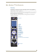
Mio Modero® R-4 Remote Mio Modero® R-4 Remote Overview The Mio Modero® R-4 remote provides custom control features, contained in an elegant handheld rechargeable device. The Mio R-4 communicates with a NetLinx master via a wireless ZigBee network, making the Mio R-4 a mobile touch panel device. Selecting a source device sends a command to the master and runs predetermined events associated with that source.
Mio Modero® R-4 Remote Touch And Tilt Sensor The Mio R-4 wakes up upon touching the chrome side rails, touching the touch screen, or pressing a button. If the remote times out when holding it, you can reawaken the device by tilting it. Errant jostling, such as a bumped table, will not wake the device unless you are holding it.
Mio Modero® R-4 Remote Page Features The Mio R-4 device supports the following display features: General Buttons Bargraphs Multistate General Buttons Multistate Bargraph Buttons Joystick Buttons Animated Icons List Buttons Marquee Text These features can be implemented using TPDesign4 v2.7 or higher. Refer to the TPDesign4 online help or Instruction Manual for details. Device Navigation The Mio R-4 allows you to scroll pages using the up and down buttons beneath the touch screen (FIG. 1).
Mio Modero® R-4 Remote 4 Mio Modero R-4
Mio R-4 Setup Mio R-4 Setup Inserting or Replacing the Lithium-Ion Battery Into the Mio R-4 To install your lithium-ion battery into the Mio R-4: 1. Flip and turn the Mio R-4 so that the buttons are facing away from you and the device is upside down. 2. Holding the device in both hands, place your thumbs on the battery door and slide the battery door free. The battery door should slide toward the bottom end of the device. 3. Connect the terminal end of the Lithium Ion battery to the port shown in FIG. 2.
Mio R-4 Setup Battery Low Indicator When the battery charge level is too low to sustain continuous operation, the Mio R-4’s touchscreen will display a popup window reading "Battery Low" as an initial warning, and then a popup window reading "Battery Very Low" to encourage the user to shut it down. The device will then shut down to prevent a total discharge of the battery.
Mio R-4 Setup 9. Place the top assembly back down on the PCB and turn the unit over again, exposing the 6 screw points. 10. Tighten the 6 screw points. 11. Install the battery, replace the battery door, and slide the door to lock it in place.
Mio R-4 Setup 8 Mio Modero R-4
Device Setup Pages Device Setup Pages Overview The Mio R-4 features onboard Setup pages that allow you to set and check the following features: Project Information functions (page 10) Remote & Display Settings (page 11) Date/Time Settings (page 15) Sound Settings (page 17) Battery Settings (page 18) Protected Settings(page 19) FIG. 4 Setup Page Menu Accessing the Setup Pages To enter Setup Menu: Hold the Input and Back buttons (see FIG. 1) for 6 seconds.
Device Setup Pages Project Information The Project Information page displays information specific to the TPDesign4 remote file currently located on the Mio R-4. Use the up and down arrows to scroll from viewable page to page. FIG. 5 Mio R-4 Project Information Pages Project Information File Name The name of the file as it was created in the designing application. Designer ID The ID of the designer for the control pages. File Revision The revision number for the control pages.
Device Setup Pages Remote & Display Settings The device provides you with information concerning current displays settings and allows you to edit the timeout and brightness. Use the up and down arrows to scroll from viewable page to page. FIG. 6 Remote & Display Settings Pages Remote & Display Settings Mio Modero R-4 Display Timeout The valid display timeout times are 0, 10, 15, 20, 25, and 30 seconds.
Device Setup Pages Remote & Display Settings (Cont.) High Port The highest port number specified in the project pages. High Address The highest address specified in the project pages. High Channel The highest channel specified in the project pages. High Level The highest level specified in the project pages Refresh Rate The refresh rate, in screen lines, of the Setup page screen display. Screen Width The width (in pixels) of the Setup page screen display.
Device Setup Pages Make sure to adjust the Sleep Timeout period after disengaging the Sleep on Display Timeout function. From the factory, the default sleep timeout will be set for 15 minutes, but engaging and then disengaging the Sleep on Display Timeout function will reset the period for 0 minutes (will not sleep until the battery charge runs low) because the previous setting will already have 0 for that setting, even though it was not actually used. 5.
Device Setup Pages Checking remote display settings 1. Select Remote & Display Settings from the Setup Page. 2. Use the device’s arrow down to navigate to the fourth and fifth Display Settings pages. 3. Select the Back button until you are out of the Setup Menu.
Device Setup Pages Date/Time Settings The date and time can be set on the device or you can use the NetLinx Master to establish the time and format used. Use the up and down arrows to scroll from viewable page to page. FIG. 8 Date/Time Settings Pages Date/Time Settings Set Date & Time Allows the user to get date and time information from the NetLinx master or to save manual changes. Time Format Selects between displayed standard and military time formats. Date Format Selects displayed date format.
Device Setup Pages Setting the date format 1. Select Date/Time Settings from the Setup Page. 2. Use the Up and Down arrows under Date Format to toggle through the formats. The Date Format currently selected is displayed between the arrows. 3. Select the Back button until you are out of the Setup Menu. Setting the date 1. Select Date/Time Settings from the Setup Page. 2. Select Date/Time Settings: 2 of 3. 3. Use the Up and Down arrows under Year, Month and Day to increment each by 1 until correct. 4.
Device Setup Pages Sound Settings The device can provide an audible indicator of both hit and miss of button selections. FIG. 9 Sound Settings Page Sound Settings Volume Adjusts the volume of the sound. Mute Silences any button sound. Play Test Plays a test tune consisting of a single octave of the musical scale. Button Hit Enables the sound of a correctly chosen button. Button Miss Enables the sound of an incorrectly chosen button. Setting the volume 1.
Device Setup Pages Battery Settings Check the battery and charging status from this page. FIG. 10 Battery Settings Pages Battery Settings Battery Charge The quality of the charge is indicated by the number of green lights versus red lights in the display. The more green lights, the higher the charge. While on the charger, the Battery Charge indicator will always show a full bar of green lights. Dock Status Indicates whether the device is in the charging cradle.
Protected Settings Menu Protected Settings Menu Overview Some of the device settings are security sensitive or change the way the device behaves. These are considered Protected Settings. The Protected Settings Menu (FIG. 12) is accessed via the Protected Settings button in the Startup Menu (FIG. 4). FIG.
Protected Settings Menu Password Entry The Password Confirmation page protects the device’s system settings, network information and calibration from casual changes. Use the Numeral Keypad pushbuttons (FIG. 1) to enter passwords. The unit allows both numeric and alphanumeric passwords, with different procedures for entering each type. FIG.
Protected Settings Menu Options & Recovery Page The Options & Recovery page (FIG. 14) enables you to enable page tracking and function identification features, as well as to reset system settings and remove all currently loaded user pages. FIG. 14 Options & Recovery Page Options & Recovery Device Number The device’s NetLinx Device Number. Function Show When enabled, displays the function codes for each button push. Page Tracking When enabled, reports all page flips to the NetLinx master.
Protected Settings Menu Toggling the Page Tracking option The NetLinx master will track all page flips if the String handler for the device Data event is set in the NetLinx code. 1. Select Options & Recovery in the Protected Settings Menu. 2. Select Page Tracking; page tracking will start when the button turns green. 3. To disable page tracking, select Page Tracking again, and the button will return to blue. 4. Select the Back button until you are out of the Setup Menu. Resetting System Settings 1.
Protected Settings Menu Protection FIG. 15 Protection Page To enable Front Button Setup Access: 1. Select Options & Recovery in the Protected Settings Menu. 2. Press the Down arrow to access the Protection page (FIG. 15). 3. To enable Front Button Setup Access, press the button, which will turn green. To disable Front Button Setup Access, press the button again to return it to blue. 4. Select the Back button until you are out of the Setup Menu.
Protected Settings Menu Edit Passwords The Edit Passwords page manages multiple passwords for the device. The first four passwords can be used to protect access to the specific pages in each project. Password 5 is for access to the protected setup pages. FIG. 16 Edit Passwords Page Changing the device password 1. Select Protected Settings in the Setup Menu. 2. Select Change Passwords on the Protected Settings Menu. 3. Select one of the five passwords to be changed.
Protected Settings Menu Calibrate To make sure that button selections behave as expected, calibrating the touch screen area may be necessary. The system will ask the user to touch crosshairs that appear in different portions of the screen. FIG. 17 Calibrate Page Calibrating the touch screen area 1. Select Calibrate from the Protected Settings Menu. 2. Touch each target that appears on the screen. 3. If successfully calibrated, the Mio R-4 will return you to the Protected Settings Menu.
Protected Settings Menu System Settings The System Settings pages (FIG. 18) provide you with the connection status, gateway selection, and RF link information. Use the device’s up and down arrows to move from page to page. FIG. 18 System Settings Pages Status Status Green light indicates the overall connection is good. Connected to System Shows the number of the connected system. Master IP The IP of the connected master. Gateway IP The IP for the Gateway providing the connection.
Protected Settings Menu Checking the master IP address 1. Select Protected Settings in the Setup Menu. 2. Select System Settings in the Protected Settings Menu. The master IP is indicated on the first page. 3. Select the Back button until you are out of the Setup Menu. Checking the gateway IP address 1. Select Protected Settings in the Setup Menu. 2. Select System Settings in the Protected Settings Menu. The gateway IP is indicated on the first page. 3.
Protected Settings Menu 6. Reboot the Mio R-4 from the Reboot Page (see the Reboot Page section on page 30). In addition to the Abort button, should you decide not to change the Device Number for any reason, press the Back button (FIG. 1) to return to the last page displayed. 7. Select the Back button until you are out of the Setup Menu. Changing the Master Connection Type 1. Select Protected Settings in the Setup Menu. 2. Select System Settings in the Protected Settings Menu. 3.
Protected Settings Menu Site Survey The Site Survey page (FIG. 19) is a report of the wireless networks found and the status of their availability to the device. Access the Site Survey page from the System Settings page. FIG. 19 Site Survey Page Site Survey PAN ID The Personal Area Network ID. Join The availability of the network. Yes indicates that it is open to join. Stack Profile The Stack Profile indicates the capabilities of that wireless network. Channel The current channel of the PAN.
Protected Settings Menu Reboot Page Some changes to the settings of the device require a reboot before the changes are accepted. This may be accessed through the Reboot page (FIG. 20). FIG. 20 Reboot Page Rebooting the device 1. Select Protected Settings from the Setup Page. 2. Select Reboot Panel. 3. Select Reboot. Test Pages The Test Pages are for testing the Mio R-4’s touchscreen. To check the touchscreen: 1. Select Protected Settings from the Setup Page. 2. Select Test Pages. 3.
Programming the Mio R-4 Programming the Mio R-4 Overview Most functionality of the Mio R-4 is handled using the application TPDesign4. Go to www.amx.com for the supporting documentation. The Mio R-4 recognizes a select number of NetLinx Commands. For a full list and descriptions, consult the SEND_COMMANDs section on page 41. Before doing any programming for the Mio R-4, you must download and install the latest AMX USB LAN driver from www.amx.com.
Programming the Mio R-4 7. Disconnect the USB cable after the download. The Mio R-4 will self-reboot after the file download. If you know that remote communication needs to be made through ZigBee after rebooting, change the Master Connection Type to Mesh after the download. Downloading Configuration Files through TPDesign4 TPDesign 4 may also be used to download configuration files to the Mio R-4. To download files directly from TPDesign 4: 1.
Programming the Mio R-4 USB NetLinx Studio can be set up to run a Virtual Master where the PC acts as the Master by supplying its own IP Address for communication to the Mio R-4. For a PC to establish a USB connection with a Mio R-4, it must have the AMX USBLAN driver installed. The AMX USBLAN driver for Windows XP can be downloaded as a stand-alone application from www.amx.com.
Programming the Mio R-4 10. Click the OnLine Tree tab in the Workspace window to view the devices on the Virtual System. 11. Right-click on Empty Device Tree/System and select Refresh System to re-populate the list. The Mio R-4 will not appear as a device below the virtual system number (in the Online Tree tab) until both the system number (default = 1) is entered into the Master Connection section of the System Settings page and the Mio R-4 is restarted.
Programming the Mio R-4 Programming Numbers The following information provides the programming numbers for colors, fonts, and borders. Colors can be used to set the colors on buttons, sliders, and pages. The lowest color number represents the lightest color-specific display; the highest number represents the darkest display. For example, 0 represents light red, and 5 is dark red. RGB triplets and names for basic 88 colors RGB Values for all 88 Basic Colors Mio Modero R-4 Index No.
Programming the Mio R-4 RGB Values for all 88 Basic Colors (Cont.) 36 Index No.
Programming the Mio R-4 RGB Values for all 88 Basic Colors (Cont.) Index No. Name Red Green Blue 81 Grey10 85 85 85 82 Grey12 51 51 51 83 Grey13 34 34 34 84 Grey2 221 221 221 85 Grey11 68 68 68 86 Grey14 17 17 17 87 Black 0 0 0 255 TRANSPARENT 99 53 99 Fixed Fonts and ID numbers Font styles can be used to program the text fonts on buttons, sliders, and pages. The following chart shows the default font type and their respective ID numbers generated by TPDesign4.
Programming the Mio R-4 Slider/Cursor Names Slider/Cursor Names Bargraph Slider Names Joystick Cursor Names None None Ball Arrow Circle -L Ball Circle -M Circle Circle -S Crosshairs Precision Gunsight Rectangle -L Hand Rectangle -M Metal Rectangle -S Spiral Windows Target Windows Active View Finder Border Styles by Numbers Border styles can be used to program borders on buttons, sliders, and popup pages. Border Styles by Numbers No. Border styles No.
Programming the Mio R-4 TPD4 Border Styles by Name (Cont.) Mio Modero R-4 No. Border styles No.
Programming the Mio R-4 TPD4 Border Styles by Name (Cont.) No. Border styles No.
Programming the Mio R-4 SEND_COMMANDs Below is a list of SEND_COMMANDs accepted by the Mio R-4 from NetLinx masters. To use these commands, establish a Telnet session from the PC to the NetLinx master. Additionally, you could use NetLinx Studio 2.4 or the master’s web page to send the commands. All text is based on a Unicode index. Page Commands Page Commands are used in the NetLinx Programming Language and are case insensitive.
Programming the Mio R-4 Page Commands (Cont.) @DPG Delete a specific popup page from a specified popup group if it exists. Delete a popup Syntax: page from a group SEND_COMMAND ,"'@DPG-;'" Variables: • popup page name = 1 - 50 ASCII characters. Name of the popup page. • popup group name = 1 - 50 ASCII characters. Name of the popup group. Example: SEND_COMMAND Device,"'@DPG-Popup1;Group1'" Deletes the popup page 'Popup1' from the popup group 'Group1'.
Programming the Mio R-4 Page Commands (Cont.) @PHT Set the hide effect time for the specified popup page. Set the hide effect Syntax: time for a popup SEND_COMMAND ,"'@PHT-;'" page Variables: • popup page name = 1 - 50 ASCII characters. Name of the page the popup is displayed On. • hide effect time = Given in 1/10ths of a second. Example: SEND_COMMAND Device,"'@PHT-Popup1;50'" Sets the Popup1 hide effect time to 5 seconds.
Programming the Mio R-4 Page Commands (Cont.) @PPK Deactivate a popup page from all pages Kill a specific popup page from all pages. Kills refers to the deactivating (Off) of a popup window from all pages. If the pop-up page is part of a group, the whole group is deactivated. This command works in the same way as the 'Clear Group' command in TPDesign4. Syntax: SEND_COMMAND ,"'@PPK-'" Variable: • popup page name = 1 - 50 ASCII characters. Name of the popup page.
Programming the Mio R-4 Page Commands (Cont.) @PPT Set a specific popup page to timeout within a specified time. Timeout is in 1/10 seconds. If timeout is empty, popup page will clear the timeout. Set a popup page to timeout within a Syntax: specified time SEND_COMMAND ,"'@PPT-;'" Variables: • popup page name = 1 - 50 ASCII characters. Name of the popup page. • timeout = timeout duration in 1/10ths of a second.
Programming the Mio R-4 Page Commands (Cont.) PPOF Deactivate a popup page Deactivate a specific popup page on either a specified page or the current page. If the page name is empty, the current page is used (see example 2). If the popup page is part of a group, the whole group is deactivated. This command works in the same way as the 'Hide Popup' command in TPDesign4. Syntax: SEND_COMMAND ,"'PPOF-;'" Variables: • popup page name = 1 - 50 ASCII characters.
Programming the Mio R-4 "^" Button Commands with Embedded Codes These Button Commands are used in the NetLinx protocol and are case insensitive. All commands that begin with "^" have the capability of assigning a variable text address range and button state range. A device must first be defined in the NetLinx programming language with values for the Device: Port: System (in all programming examples - Remote is used in place of these values).
Programming the Mio R-4 "^" Button Commands with Embedded Codes ^BMF (Cont.) For some of these commands and values, refer to theRGB Values for all 88 Basic Colors table on page 35. • ’%CF’ = Set Fill Color. • ’%CB’ = Set Border Color. • ’%CT’ = Set Text Color. • ’%SW<1 or 0>’ = Show/hide a button. • ’%ST