Operation/Reference Guide Mio Modero ® Device Family Control System Accessories Last Revised: 09/05/2008
AMX Limited Warranty and Disclaimer AMX warrants its products to be free of defects in material and workmanship under normal use for three (3) years from the date of purchase from AMX, with the following exceptions: • Electroluminescent and LCD Control Panels are warranted for three (3) years, except for the display and touch overlay components that are warranted for a period of one (1) year.
Software License and Warranty Agreement LICENSE GRANT. AMX grants to Licensee the non-exclusive right to use the AMX Software in the manner described in this License. The AMX Software is licensed, not sold. This license does not grant Licensee the right to create derivative works of the AMX Software. The AMX Software consists of generally available programming and development software, product documentation, sample applications, tools and utilities, and miscellaneous technical information.
Table of Contents Table of Contents Overview ............................................................................................................1 Specifications............................................................................................................ 2 Available Color Schemes........................................................................................... 3 Mio Modero LCD Feature .........................................................................................
Table of Contents ii Mio Modero Device Family
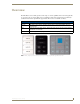
Overview Overview The Mio Modero device family provides a wide range of control capabilities in the form of keypads that are as adept as they are elegant. Each device is available as single style (8 button max) or double style (16 button max) with an optional LCD capped button. The devices are available as follows: Mio Modero Device Family Classic Engraved plastic buttons with a red (active) feedback LED in the upper left corner.
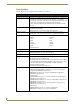
Overview Specifications The Mio Modero device family keypad specifications are as follows: Specifications Power: 12 vDC, 70 - 230 mA (range depending on device type and number of buttons) Front Panel Components: • LCD (where applicable) - SPI controlled 96 x 96 pixel resolution, monochrome FSTN display with a white Electroluminescent backlight; an active button. • Pushbuttons - a maximum of 8 buttons on the single style and 16 buttons on the double style.
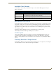
Overview Available Color Schemes The Mio Modero device family is available in a range of colors, and the Elite supports a variety of Lutron color schemes.
Overview 4 Mio Modero Device Family
Installation Installation Before touching the device, discharge the static electricity from your body by touching a grounded metal object. The basic front and rear components of the Mio Modero are as follows: Installation Button AxLink 3.5 mini Phoenix connector Slot to pry button free PWR+ Screw holes 8 position mini DIP switch Notch to pry faceplate free (Rear Single) (Front Single) 8 position mini DIP switch AxLink 3.
Installation Mounting Frame LCD Installation Buttons Faceplate FIG. 3 Sections of The Mio Modero Changing Buttons The Mio Modero Classic and Elite are shipped with "installation" buttons; they are intended to be place holders until your engraved buttons, designed with KeypadBuilder, arrive. To switch out "installation" buttons: 1. Pry the button using the slot on the front of the "installation" buttons to remove them from the Mio Modero. 2.
Installation To change custom buttons: 1. If connected, disconnect the power supply. 2. If connected to mounting frame, place a flathead screwdriver in the notch at the bottom right of the Mio Modero, and pry the faceplate from the mounting frame. 3. On the back of the faceplate locate the button access points, outlined with white circles. Using a straightened paperclip, poke through the button access points until the buttons pop free. 4. Snap the desired custom buttons into place.
Installation Setting The AxLink Device Number 1. If connected, disconnect the power supply. 2. Locate the 8-position Device DIP switch on the rear panel.(FIG. 5). 3. Set the DIP switch according to the switch values shown below. Switch 1 2 3 4 5 6 7 8 Value 1 2 4 8 16 32 64 128 The device number is set by the total value of DIP switch positions that are ON (up). As an example, the DIP switch in FIG. 5 defines device number 129 (1+128=129). FIG.
Installation Wiring guidelines The Mio Modero requires 12 VDC power to operate properly. The necessary power is supplied via the AxLink cable. The maximum AxLink wiring distance is determined by power consumption, supplied voltage, and the wire gauge used for the cable. The following table lists wire sizes and the maximum lengths allowable based on the maximum power consumption rating of 170 mA. Wiring Guidelines at 170 mA Wire Size Maximum Wiring Length 18 AWG 690.42 feet (210.43 m) 20 AWG 436.
Installation Using AxLink for data with an auxiliary power supply Connect the controller’s AxLink connector to the AxLink connector on the rear panel of the Mio Modero device, as shown in FIG. 7. PWR (+) 12 VDC power supply GND (-) PWR (+) AXP AXM GND (-) PWR (+) AXP AXM GND (-) Controller Mio Modero device (3.5 mm connector) FIG. 7 AxLink and 12 VDC power supply wiring diagram If you are not using power from AxLink, disconnect the wiring from the controller before wiring the Mio Modero device.
Installation Mounting Procedures FIG. 8 shows the wallbox mounting dimensions for the single and double style Mio Modero. AMX recommends mounting the Mio Modero in a standard one-gang wallbox, a conduit box per NEC specs section 370, with a minimum internal clearance of 2-5/8" x 1-3/4" x 1-5/8" (HWD), but it is possible to mount the Mio Modero to a podium without a wallbox. 2.000 [50.8 MM] 3.282 [83.4 MM] 2.250 [57.2 MM] FIG.
Installation 2.000 [50.8 MM] 3.282 [83.4 MM] 2.250 [57.2 MM] FIG. 9 Mio Modero Double Style mounting dimensions Wallbox Mounting 1. Use the cutout dimension for the wallbox to cutout the install surface for the Mio Modero. 2. Confirm that the terminal end of the AxLink cable is disconnected, and not receiving power. 3. If the faceplate is connected to the mounting frame, place a flathead screwdriver in the notch at the bottom right of the Mio Modero, and pry the faceplate from the mounting frame. 4.
Installation FIG. 10 Attaching the faceplate to the mounting frame Podium Mounting 1. Use the cutout dimension shown in either FIG. 8 or FIG. 9 to cutout the mounting frame install surface for the Mio Modero. 2. Confirm that the terminal end of the AxLink cable is disconnected, and not receiving power. 3. If the faceplate is connected to the mounting frame, place a flathead screwdriver in the notch at the bottom right of the Mio Modero, and pry the faceplate from the mounting frame. 4.
Installation Accent Frame While the Mio Modero device family does fit into many International wallboxes, it may be necessary to utilize the optional accent frame to completely cover the wallbox. To install the Mio Modero with the optional accent frame: 1. Use the cutout dimension for the wallbox to cut out the install surface for the Mio Modero. 2. Place the accent frame on the wallbox; align the screw holes with the mounting holes on the wallplate. Fasten the wallplate to the wallbox.
Mio Modero IR Mio Modero IR The Mio Modero IR (FIG. 11) is a remote IR receiver for use with NetLinx® Central Controllers and operates via the AxLink bus to remotely control devices. The Mio Modero IR is in a wall panel that fits into the US-style single-gang enclosure and most International single-gang enclosures. The Mio Modero IR works with AMX 38 kHz and 455 kHz IR transmitters. Faceplate IR Cover Mounting Frame FIG.
Mio Modero IR Wiring and Installation Set the receive AxLink device number before installing the Mio Modero IR. FIG. 12 illustrates the location of key components on the Mio Modero IR circuit board. AxLink 3.5 mini Phoenix connector PWR+ Screw holes 8 position mini DIP switch Notch to pry faceplate free (Rear Single) FIG. 12 Location of key components on the Mio Modero IR circuit board Setting the AxLink Device Number 1. If connected, disconnect the power supply. 2.
Mio Modero IR Wiring Guidelines The Mio Modero IR requires 12 VDC power to operate properly. The power is supplied by the AMX system's AxLink cable. The maximum wiring distance between the Central Controller and the receiver is determined by power consumption, supplied voltage, and the wire gauge used for the cable. The following table lists wire sizes and the maximum lengths allowable between the receiver and the Central Controller. The maximum wiring lengths are based on a minimum of 13.
Mio Modero IR Mounting Procedure FIG. 15 shows the wallbox mounting dimensions for the Mio Modero IR. AMX recommends mounting the Mio Modero IR in a standard one-gang wallbox, a conduit box per NEC specs section 370, with a minimum internal clearance of 2-5/8" x 1-3/4" x 1-5/8" (HWD). 2.000 [50.8 MM] 3.282 [83.4 MM] 2.250 [57.2 MM] FIG. 15 Mio Modero IR mounting dimensions 1. Use the cutout dimension for the wallbox to cutout the install surface for the Mio Modero IR. 2.
Mio Modero IR FIG.
Mio Modero IR 20 Mio Modero Device Family
Programming The Mio Modero Programming The Mio Modero KeypadBuilder Most functionality of the Mio Modero is handled using the application, KeypadBuilder. Go to www.amx.com for the KeypadBuilder Instruction Manual. There are a select number of SEND_COMMANDs the Mio Modero recognizes. Recognized SEND_COMMANDs Below is a list of SEND_COMMANDs accepted by the Mio Modero device family from NetLinx masters. As indicated, not every command applies to all Mio Modero devices, e.g.
Programming The Mio Modero SEND_COMMANDs (Cont.) ^CFG Combine/Uncombine adjacent buttons Syntax: "'^CFG- '" Variables: command value = (1= combine, 0= uncombine). Example: SEND_COMMAND Panel,"'^CFG-1'" Set the Key Pad to button combine mode @CST Sets the display contrast for the device. Syntax: "'@CST-'" Variables: Contrast Level = a value from 0 - 31. Example: SEND_COMMAND Panel,"'@CST-15'" Sets the display contrast to approximately 50%.
Programming The Mio Modero SEND_COMMANDs (Cont.) ^FML D L # Sets a line of the display to a dynamic line with a level, and sets the level style Syntax: "'^FML-,D,L,'" Variables: variable text address range = 1 - 4; the address range corresponds to the dynamic line number.
Programming The Mio Modero SEND_COMMANDs (Cont.) ^SHO Show or hide text with a set variable text range. Syntax: "'^SHO-,'" Variables: variable text address range = 1 - 4; the address range corresponds to the dynamic line number. command value = (0= hide, 1= show). Example: SEND_COMMAND Panel,"'^SHO-1,0'" Hides text on dynamic line 1 of the LCD button. SLEEP Force the device into screen saver mode.
Programming The Mio Modero SEND_COMMANDs (Cont.) ^TXT(LCD equipped only) Assign a text string to those LCD buttons with a defined address range. Sets nonunicode text. Syntax: "'^TXT-,'" Variables: variable text address range = 1 - 4; the address range corresponds to the dynamic line number. new text = 1 - 20 characters (uses one byte Unicode values for all text characters). Example: 1.
Programming The Mio Modero Sending Firmware to The Mio Modero Keypads You need NetLinx studio to update firmware located on the Mio Modero Keypads. To send firmware to the keypads: 1. Open NetLinx Studio. 2. Go to Tools > Firmware Transfers > Send to Axcess Device... This opens the Send to Axcess Dialog Window . FIG. 17 Send to Axcess Dialog Window 3. Browse to the location of the firmware file. 4. Select the file within the Files frame. 5. Click Query for Devices. 6.
Programming The Mio Modero Mio Modero Device Family 27
AMX. All rights reserved. AMX and the AMX logo are registered trademarks of AMX. AMX reserves the right to alter specifications without notice at any time. ©2007 9/08 It’s Your World - Take Control™ 3000 RESEARCH DRIVE, RICHARDSON, TX 75082 USA • 800.222.0193 • 469.624.8000 • 469-624-7153 fax • 800.932.6993 technical support • www.amx.