
Corporation Home Security System Operation/Reference Guide


Wiring and Connections
10
Metreau Entry Communicators
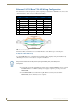
Ethernet 10/100 Base-T RJ-45 Wiring Configuration
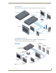
The table below describes the pinouts, signals, and pairing for the Ethernet 10/100 Base-T connector and
cable. The Ethernet cable connection is illustrated in FIG. 7.
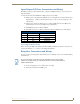
The Metreau Entry Communicators use CAT5/CAT6 wire via the Ethernet port for PoE power.
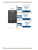
PoE (Power Over Ethernet)
Use the PS-POE-AF Power over Ethernet Injector (FG423-80) to simplify wiring and installation by
eliminating the need for an AC outlet at each point of installation.
If used with a non PoE-capable Ethernet switch (such as the NXA-ENET24), then an optional
PS-POE-AF Power-over-Ethernet (PoE) power supply is required to provide power to the
MET-ECOM.
If the MET-ECOM is used with a PoE-capable Ethernet switch (such as the NXA-
ENET24PoE), then no PoE Injectors are required.
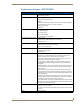
Ethernet Pinouts and Signals
Pin Signals Connections Pairing Color
1 TX + 1 --------- 1 1 --------- 2 White-Orange
2 TX - 2 --------- 2 Orange
3 RX + 3 --------- 3 3 --------- 6 White-Green
4 no connection 4 --------- 4 Blue
5 no connection 5 --------- 5 White-Blue
6 RX - 6 --------- 6 Green
7 no connection 7 --------- 7 White-Brown
8 no connection 8 --------- 8 Brown
FIG. 7
RJ-45 Wiring Diagram
Entry Communicator Unit can be placed up to approximately 330’ (100 meters) from
PoE Injector.