Operation/Reference Guide Metreau™ Entry Communicators MET-ECOM Metreau Entry Communicator MET-ECOM-D Metreau Entry Communicator with Display Voice and V i de o Commu nication Sy stems Last Revised: 12/04/2008
AMX Limited Warranty and Disclaimer This Limited Warranty and Disclaimer extends only to products purchased directly from AMX or an AMX Authorized Partner which include AMX Dealers, Distributors, VIP’s or other AMX authorized entity.
Table of Contents Table of Contents Metreau Entry Communicators ...........................................................................1 Overview .................................................................................................................. 1 Front Components .......................................................................................................... 2 Rear Components.......................................................................................................
Table of Contents Installing the Metreau Entry Communicator.................................................................. 27 Using Zero Configuration .................................................................................29 Overview ................................................................................................................ 29 Bonjour (Zero-Configuration) Client........................................................................
Table of Contents Programming ....................................................................................................51 Overview ................................................................................................................ 51 SEND_COMMANDs ................................................................................................ 51 Touch Panel Intercom Commands .................................................................................
Table of Contents Setup page.................................................................................................................... 76 Someone At The Door page ......................................................................................... 77 Creating Popup Pages ............................................................................................ 78 Door Answer Call popup page .....................................................................................
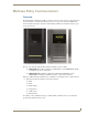
Metreau Entry Communicators Metreau Entry Communicators Overview The Metreau Entry Communicators (FIG. 1) can be placed at entry points of homes, condos and hotels to provide audio/video communications with anyone at a door or gate - all over IP. Any AMX Modero intercom-enabled touch panel can interface with the Entry Communicator and allow residents to open doors, gates and more. FIG.
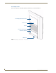
Metreau Entry Communicators Front Components The front components of the Metreau Entry Communicators are indicated in FIG. 2: OLED display (MET-ECOM-D only) Video Camera Speaker Dual Color LED Status Bar Pushbutton (Doorbell) Microphone FIG.
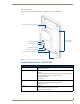
Metreau Entry Communicators Rear Components The rear components of the Metreau Entry Communicators are indicated in FIG. 3: Camera Viewing Angle Adjustment Mounting Slots (2 on each side) ID/Reset pushbutton STATUS (green LED) Ethernet Connection 2 Multi-Purpose I/Os (5V) 2 Low Voltage Relays (1A Contact) Mounting Clip FIG.
Metreau Entry Communicators MET-ECOM Specifications (Cont.) Microphone: • -40 dB sensitivity, built-in echo cancellation (telephone quality) • Full duplex communication • VoIP Telephony Rear Panel Components: • Camera Viewing Angle Adjustment • Ethernet Port - 10/100 Ethernet with PoE. LEDs show communication activity, connection status, speeds, and mode information: SPD (speed) - Green LED lights On when the connection speed is 100 Mbps and turns Off when the speed is 10 Mbps.
Metreau Entry Communicators Product Specifications - MET-ECOM-D MET-ECOM-D Specifications Power: • PoE powered – no local Power Supply needed Front Panel Components: • OLED Display • IEEE 802.3af Compliant • Integrated Color Video Camera • Speaker • Dual Color LED Status Bar: (Yellow/ Red) can be used to provide feedback, to attract attention for action, or as general indicator. • Pushbutton (Doorbell) • Microphone OLED Display: • 4-bit Gray Scale • 1.
Metreau Entry Communicators MET-ECOM-D Specifications (Cont.) Operating Environment: 32° to 104° F (0° to 40° C) Mounting: The MET-ECOM-D is installed in several ways: • 4 screws for hard surface mounting • 2 expansion clips for pressure mounting • Using the optional Surface Mount Box Colors Available: • • • • • • Included Accessories: • Installation Kit (FG039-12) - includes front mount flange, 4 installation screws (#4-40 x 3.12), 2 Phoenix connectors (female, 3.5mm) and a Ferrite clip.
Positioning the Camera Positioning the Camera Overview The camera on the Metreau Entry Communicators provides a symmetrical 42° viewing angle, and by default the camera is centered. The Metreau Entry Communicators feature a Camera Viewing Angle Adjustment slider on the rear panel of the unit that allows you to adjust the viewing angle horizontally from -15° to 15°. FIG. 4 indicates the viewing range of the integrated camera in the Metreau Entry Communicators.
Positioning the Camera Top view when camera is centered at 0° L R 42° Camera Viewing Angle Adjustment slider (default) Camera Top view when camera is facing left at 15° L R 42° Camera Top view when camera is facing right at 15° 42° L R Camera FIG.
Wiring and Connections Wiring and Connections Overview To avoid any damage to the electronic component, installation must be performed in an ESD safe environment. The installation section addresses the mounting and wiring of the Metreau Entry Communicators. After you have completed the installation you must consult the Using the Configuration Manager section of the Metreau Entry Communicators Operation/Reference Guide (available online at www.amx.com).
Wiring and Connections Ethernet 10/100 Base-T RJ-45 Wiring Configuration The table below describes the pinouts, signals, and pairing for the Ethernet 10/100 Base-T connector and cable. The Ethernet cable connection is illustrated in FIG. 7.
Wiring and Connections Input/Output (I/O) Port: Connections and Wiring The I/O port responds to either switch closures, voltage level (high/low) changes, or it can be used for logic-level outputs. A contact closure between the GND and an I/O port is detected as a Push. When used for voltage inputs, the I/O port detects a low signal (0 - 1.5 VDC) as a Push, and a high signal (3.5 - 5 VDC) as a Release (this IO port uses 5V logic but can handle up to 12V without harm).
Wiring and Connections Ferrite Installation (Required) Metreau Entry Communicators comes with a Cat5 Suppression Ferrite that must be clipped around the Ethernet cable, inside the wall box (no tools required). 1. Release the latch to open the plastic enclosure. 2. Insert the Cat5 cable and close the enclosure. 3. Installation complete. FIG.
Wiring and Connections System Diagram FIG. 10 provides a basic NetLinx system diagram using Metreau Entry Communicators: NetLinx Master MVP-8400i MVP-5200i NXA-ENET24PoE NXA-WAP250G PS-POE-AF NXD-1000Vi NXD-700Vi MET-ECOM-D MET-ECOM FIG. 10 Metreau Entry Communicators - System Diagram System Diagram - Intercom The following system diagram (FIG. 11) illustrates an AMX system using Metreau Entry Communicators with both wired and wireless touch panels: FIG.
Wiring and Connections 14 Metreau Entry Communicators
Mounting and Installation Mounting and Installation MET-ECOM / MET-ECOM-D Installation Overview This section addresses the physical mounting of the MET-ECOM and MET-ECOM-D Metreau Entry Communicators. To avoid any damage to the electronic component, installation must be performed in an ESD safe environment. Also note that the Metreau Entry Communicator and wall box must have an earth-ground. Dimensions FIG.
Mounting and Installation Mounting Specifications The following illustrations (FIG. 13, FIG. 14 and FIG. 15) provide mounting specifications for the Metreau Entry Communicators conduit box (FG. Reference these measurements when planning and installing the device. Front View FIG.
Mounting and Installation Side Views FIG. 14 Mounting Specifications (side views) Top View FIG.
Mounting and Installation Typical Installation (Without Expansion Clips) FIG. 16 provides specifications for mounting the wall box without the use of expansion clips. FIG. 16 Typical Installation (Without Expansion Clips) Be sure to install the Cat5 Suppression Ferrite (provided) before mounting the Metreau Entry Communicator unit into the wall box. Refer to the Ferrite Installation (Required) section on page 12 for details. 1.
Mounting and Installation Rough-in installation tabs Keyhole Ethernet cable access Expansion clip installation tabs Earth ground point FIG. 17 Metreau Entry Communicators wall box The device and wall box must have an Earth ground. 5. Install the (provided) Ferrite clip onto the Ethernet cable (see FIG. 8 on page 12). 6. Connect the Ethernet cable in the back of the Metreau Entry Communicator. 7. Insert the Metreau Entry Communicator into the wall box, and push until the device is flush to the wall.
Mounting and Installation Installing the Wall Box Without the Use of Tabs Be sure to install the Cat5 Suppression Ferrite (provided) before mounting the Metreau Entry Communicator unit into the wall box. Refer to the Ferrite Installation (Required) section on page 12 for details. A brick and mortar installation environment is a great example where no tabs are required. 1.
Mounting and Installation Wall Surface Installation (Using Expansion Clips) Expansion clips are mounted through the 2 holes located along the rim of the wall box (see FIG. 18). As the screw is tightened, the clip bends toward the insertion hole and into the wall. This bending creates a "grip" on the wall by either pressing onto the wall or by securing the drywall between the housing and the drywall clip.
Mounting and Installation 4. Install the 2 drywall screws and expansion clips into the 2 locations along both sides of the wall box. 5. Insert the wall box and expansion clips into the cutout until the rim of the wall box is flush against the wall. Replacement drywall clip sets must be ordered from AMX. 6. Tighten the 2 drywall clip sets (screws and clips) until the wall box is flush against the wall (FIG. 19). FIG.
Mounting and Installation 8. Install the (provided) Ferrite clip onto the Ethernet cable (see FIG. 8 on page 12). 9. Connect the Ethernet cable in the back of the Metreau Entry Communicator. 10. Insert and fasten the Metreau Entry Communicator into the wall box. Installing Into a Flat Surface Using Mounting Screws Mounting screws (#4 flathead, not included) are secured through two sets of circular holes located at the left and right sides of the wall box.
Mounting and Installation 6. Place the lug of the ground wire on the device and the Earth ground wire around the provided screw and connect them both to the point shown in FIG. 17. The device and wall box must have an Earth ground. 7. Install the (provided) Ferrite clip onto the Ethernet cable (see FIG. 8 on page 12). 8. Connect the Ethernet cable in the back of the Metreau Entry Communicator. 9. Insert and fasten the Metreau Entry Communicator into the wall box.
Mounting and Installation Using the Optional Surface Mount Box The CB-MET-ECOMS (-S/-B) Surface Mount Box Kit for Metreau Entry Communicators is available for situations where it is undesirable or impossible to install the conduit box into the mounting surface. It is available in two colors: CB-MET-ECOMS-S - paintable Silver (FG039-14-S) CB-MET-ECOMS-B - Black (FG039-14-B) The Surface Mounting Box (FIG.
Mounting and Installation Surface Mount Box Specifications FIG. 22 provides mounting specifications for the CB-MET-ECOMS: TOP SIDE REAR FRONT FIG.
Mounting and Installation Ferrite Installation (Required) The CB-MET-ECOMS comes with a Cat5 Suppression Ferrite that must be clipped around the Ethernet cable, inside the back box (no tools required). 1 2 3 (complete) FIG. 23 Installing the CAT5 Suppression Ferrite 1. Release the latch to open the plastic enclosure. 2. Insert the Cat5 cable and close the enclosure.
Mounting and Installation 1. Run all cables through the Conduit Routing Hole on the rear panel of the Surface Mounting Box. The Conduit Routing Hole is intended to accept conduit of up to 0.500" (1.27 cm) in diameter (see FIG. 22). 2. Secure the incoming conduit to the inside of the Surface Mount box. 3. Connect all cables (Ethernet, I/O & Relay) to the Metreau Entry Communicator. 4.
Using Zero Configuration Using Zero Configuration Overview Metreau Entry Communicators with firmware versions of v1.00.018 (MET-ECOM) and v1.00.020 (MET-ECOM-D) or higher support using "zero-configuration" client software to quickly install multiple devices on the network. Bonjour (Zero-Configuration) Client You can use a zero-configuration client to determine the IP address of the Metreau Entry Communicators. There are many zero-configuration clients available.
Using Zero Configuration Notice that the serial number is appended to the name of the device. In this case the serial number is 218001WHP2980023. At this point, the device can be configured (changing IP settings, NetLinx settings, User settings, etc) via the pages in the Configuration Manager (see the Using the Configuration Manager section on page 33).
Using Zero Configuration Manually set the PC's IP address to 169.254.1.1 and subnet mask to 255.255.0.0. FIG. 27 Internet Properties (TCP/IP) Properties dialog 4. Launch Internet Explorer and select the Bonjour Plug-in. 5. Double-click the MET-ECOM (Metreau-218001XXXnnnnnnn) in the Bonjour Plug-in pane and login and configure the device as needed (see Using the Configuration Manager section on page 33).
Using Zero Configuration 32 Metreau Entry Communicators
Using the Configuration Manager Using the Configuration Manager Overview Metreau Entry Communicators have a built-in web console (FIG. 28) that allows you to easily make various configuration settings via a web browser on any PC that has access to the device. The web console consists of a series of web pages that separate device configuration options by category. Collectively, the pages in the web console are referred to as the Configuration Manager.
Using the Configuration Manager Command Buttons The Configuration Manager is divided into four primary sections, indicated by four command buttons across the top of the main page (FIG. 29): FIG. 29 Configuration Manager Command Buttons Summary: The Summary of Device page is the page that is displayed when the Configuration Manager is accessed. Use the this page to view a summary of settings for this Metreau Entry Communicator (see the Summary of Settings Page section on page 35).
Using the Configuration Manager Summary of Settings Page The Summary of Device Settings page (FIG. 31) is the initial view when the Configuration Manager is accessed. FIG. 31 Summary of Device Settings Page Naturally, this page can be accessed at any time via the Summary command button at the top of the web console. Summary of Device Settings Page Device Information Device Type The name of the connected device. Firmware The version of the firmware running on the device.
Using the Configuration Manager Summary of Device Settings Page (Cont.) IP Settings IP The IP setting of the unit; either Static or Dynamic. Host The hostname of the unit. IP Address The IP address of the unit. Subnet Mask The subnet mask associated with IP addressing Gateway The IP gateway used by this unit. MAC Address The MAC address of the unit. NetLinx Settings Status The connection status of the device. System Number The NetLinx system number.
Using the Configuration Manager Configuration Page Click the Configuration command button to access the Configuration page (FIG. 32). This page contains three tabs: IP Settings (initial view): Use the options in this tab to specify Network IP settings (see below). NetLinx Settings: Use the options in this tab specify the ICSP connection to the NetLinx master (see the Configuration Page - NetLinx Settings Tab section on page 39).
Using the Configuration Manager Configuration Page - Network IP Settings Tab IP Address IP • Dynamic: IP address and subnet mask are requested from the DHCP server. • Static: User provides IP address information. Host The hostname of the unit. IP Address The IP address of the unit. Subnet Mask The IP subnet mask of the unit. Gateway The gateway used for IP routing. DNS Address Domain Suffix The domain name. Primary DNS Domain Name System IP numbers associated to the domain suffix.
Using the Configuration Manager Configuration Page - NetLinx Settings Tab Select the NetLinx Settings tab of the Configuration page to access the NetLinx Settings tab (FIG. 33). Use the options in this tab to view and edit the ICSP connection to the NetLinx master. FIG. 33 Configuration Page - NetLinx Settings tab Configuration Page - NetLinx Settings Tab Connection Mode Displays the ICSP connection status (Not Connected / Connected).
Using the Configuration Manager Setting the Host Name requires DNS implementation on the IP network. 5. If you have enabled password security on your master, you need to set the username and password within the fields provided. 6. Click Accept. 7. In the The system will need to reboot for changes to take effect window, click OK.
Using the Configuration Manager Device Utilities Page Click the Utilities command button to access the Device Utilities page (FIG. 35). The options on this page allow you to upload, change, and display images on the MET-ECOM-D. Create New Folder Image Selection field FIG. 35 Device Utilities Page Device Utilities Page Utility Meta Information Location Enter a descriptive text string that indicates the physical location of this device.
Using the Configuration Manager Device Utilities Page (Cont.) File Upload Browse Opens the file browse window, where you can locate and select Display Images. Submit Submits the selected file image for upload. Images Location The file directory location of the selected image. New Folder Creates a new folder directory. Image Selection Field Field of available images for display on the device; click to select.
Using the Configuration Manager 2. Save the file as a ".BMP" image (FIG. 37). FIG. 37 Same image - saved as a BMP file 3. Reduce the BMP image to 128 x 64 pixels. At this point there are options - you can either crop or reduce the original image to size. In many cases, a combination of cropping and resizing may be best, depending on the size and nature of the image. In this example, we will simply resize the image to 128 pixels wide by 64 pixels high (FIG. 38). FIG.
Using the Configuration Manager Check your graphics editing program for options relative to the reduction method applied to the image when reducing the colors to 1-bit. In many cases you can select from several techniques (such as error diffusion, ordered dither and/or nearest color). Depending on the nature of the image you are working with, some reduction methods will yield much better results than others.
Using the Configuration Manager Creating a New Dynamic Image 1. In TPDesign4, select Panel > Resource Manager to access the Resource Manager dialog, and open the Dynamic Images tab (FIG. 40). 2. Click the New button at the top of the dialog (see FIG. 40) to invoke the Create Dynamic Image dialog (FIG. 41). The options in this dialog allow you to name and define dynamic image resources to add to your Project. FIG. 41 Create Dynamic Image dialog 3.
Using the Configuration Manager Create Dynamic Image dialog (Cont.) • Refresh Rate: Use the up/down arrows to adjust the number of seconds between refreshes in which the resource is downloaded again. Refreshing resources will cause the button displaying that resource to refresh as well. The default value is zero (0), which means that the resource is only downloaded once.
Using the Configuration Manager Audio/Video Page Audio/Video Page - Audio Settings Tab Click on the Audio tab of the Audio/Video Page to access the Audio Settings tab (FIG. 42). Use the options in this tab to view/edit audio-specific settings. FIG. 42 Audio/Video Page - Audio Settings tab Audio/Video Page - Audio Settings Tab Audio Codec G.711 Codec An ITU-T standard for audio companding.
Using the Configuration Manager Audio/Video Page - Video Settings Tab Click the Video tab in the Audio/Video Page to access the Video Settings page (FIG. 43). Use the options in this tab to view/edit video-specific settings. FIG. 43 Audio/Video Page - Video Settings tab Audio/Video Page - Video Settings Tab Video Codec Codec • MJPEG - Motion JPEG codec. • H.263 - A low-bitrate compressed format standard codec. Note: Do not change the Video Codec setting during a call.
Using the Configuration Manager Audio/Video Page - Video Settings Tab (Cont.) Red 0 - 255 scale for the Red balance. Green 0 - 255 scale for the Green balance. Blue 0 - 255 scale for the Blue balance. Flicker Correction • Anti-flicker Mode - The device automatically compensates for flicker. • 50 Hz - Sets the flicker refresh to 50 Hz. • 60 Hz - Sets the flicker refresh to 60 Hz. Wired Frame Rate 0 - 100 rate of frame display on the device, in hard-wired installations.
Using the Configuration Manager Audio/Video Page - Display Settings Tab Contrast 0 - 255 scale for contrast display from device. Intensity 0 - 255 scale for image intensity display from device. Displaying The image currently displayed on the device. Setting the Display Settings On The Device 1. In the menu on the top of the Configuration Manager, select Audio/Video. 2. Select the tab Display. 3. Use the sliders to change the Contrast level. 4. Use the sliders to change the Intensity Rate level. 5.
Programming Programming Overview There are a select number of SEND_COMMANDs recognized by the Metreau Entry Communicators. SEND_COMMANDs Below is a list of SEND_COMMANDs supported by the Metreau Entry Communicators from NetLinx masters. To use these commands, establish a Telnet session from the PC to the NetLinx master. Additionally, you could use NetLinx Studio 2.4 or the master’s web page to send the commands. All text is based on a Unicode index.
Programming Touch Panel Intercom Commands (Cont.) STREAM-SET (Cont.) Example (H.263 video stream): SEND_COMMAND MET1, "’STREAM-SET 192.168.0.3,9000,9002,video,H263,1" SEND_COMMAND TP2, "’^ICS-192.168.0.4,9002,9000,2’" Sets up a h.263 video stream between Metreau Entry Communicators and a touch panel. Note: Do not change the Audio or Video Codec settings during a call. STREAM-GET Retrieves a description of the stream parameter being used by the current stream.
Programming Touch Panel Intercom Commands (Cont.) ^VER? Metreau Entry Communicator version number. The Metreau Entry Communicator will respond with its version number as shown in the response below. The Metreau Entry Communicator will respond with one of the following strings: Syntax: SEND_COMMAND ,"’^VER?’" Example: SEND_COMMAND MET1,"’^VER?’" Returns: VERSION xx.xxx.
Programming RTP, RTCP Video and Audio Streaming Commands (Cont.) SET AUDIO Sets the current configuration of the audio system. Configuration includes codec, sampling rate, and bit rate. Sample rate is at 8khz. Syntax: SEND_COMMAND ,"'SET AUDIO '" Variable: • Codec = OFF, G.711ALAW, G.711ULAW Example: SEND_COMMAND MET1,"'SET AUDIO G.711'" Sets the audio configuration to G.711 sampling at 8khz. Note: Do not change the Audio or Video Codec settings during a call.
Programming Face Plate LED Commands Metreau Entry Communicators support the following LED face plate SEND_COMMANDs on port 1. Face Plate LED Commands SET LED-LEVEL Syntax: Adjusts the brightness of the LED. To turn the LED ON or OFF. SEND_COMMAND ,"'SET LED-LEVEL '" Variable: • State = ON, OFF • Level = 0 – 100. Represents 0%(dimmest) to 100% brightest. Example: SEND_COMMAND MET1,'"SET LED-LEVEL ON 50'" Sets the LED brightness level ON at 50%.
Programming Camera Commands Unlike AMX touch panels, Metreau Entry Communicators return String responses instead of Command responses. The Metreau Entry Communicators Camera (MET-ECOM-D only) supports the following camera SEND_COMMANDs on port 1. Camera Commands SET CAM-WBAL Sets the white balance control setting for the camera. White balance setting allows for internal light adjustments based upon light conditions surrounding the unit.
Programming Camera Commands (Cont.) SET CAM-CST Sets the display contrast level for the camera. Syntax: "'SET CAM-CST '" Variables: • Contrast Level = a value from 0 – 100 in percentage Example: SEND_COMMAND MET1,"'SET CAM-CST 50’" Sets the display contrast to approximately 50%. GET CAM-CST Retrieves the contrast level for the camera.
Programming Camera Commands (Cont.) Syntax: GET CAM-FLICK Retrieves the flicker mode setting for the camera. "'GET CAM-FLICK’" Variables: • none Example: SEND_COMMAND MET1,"'GET CAM-FLICK’" Returns: CAM-FLICK = 50 The Camera flicker setting is at 50hz mode. LCD Commands The LCD located on the face plate (MET-ECOM-D only) supports the following SEND_COMMANDs on port 1. LCD Commands SET DISP-BANNER Syntax: Sets the banner on the LCD.
Programming LCD Commands (Cont.) SET DISP-BRT Sets the brightness level to a percentage. The LCD display supports quad (25%), half (50%) and full (100%) brightness. Syntax: "'SET DISP-BRT ,< brightness level>'" Variables: • brightness level # = a value from 25,50,100. Example: SEND_COMMAND MET1,"'SET DISP-BRIT 50’" Sets the awake brightness level to 50%. GET DISP-BRT Retrieves the Brightness level for the LCD display.
Programming I/O Commands The I/O port supports the following SEND_COMMANDs on port 2. There are two channels on port 2: Channel 1 and Channel 2; I/O Commands GET INPUT Gets the input channels active state. An active state can be high (logic high) or low (logic low or contact closure). Channel changes, Pushes, and Releases generate reports based on their active state.
Programming System Commands (Cont.) SET DOOR-DESC Set the door description text. Syntax: SEND_COMMAND ,"'SET DOOR-DESC , '" Variables: • Desc_num= 1 or 2 • Desc_txt = max 20 character string Example: SEND_COMMAND STORM,"'SET DOOR-DESC 1, front door'" Sets the 1st description to 'front door' GET DOOR-DESC Returns the door's description text.
Programming Upgrading Firmware Before beginning the Upgrade process Setup and configure your NetLinx Master. Refer to your particular NetLinx Master instruction manual for detailed setup procedures. Prepare the communication pages on the Metreau Entry Communicator for use; refer to the Using the Configuration Manager section on page 33. Refer to the NetLinx Studio version 2.4 or higher Help file for information on uploading firmware files via Ethernet.
Programming List of previously saved IP Addresses FIG. 45 Assigning Communication Settings and TCP/IP Settings 10. Click OK three times to close the open dialogs and save your settings. 11. Click Yes to interrupt the current communication from the Master and apply the new settings. 12. Select Tools > Reboot the Master Controller to access the Reboot the Master dialog, then click Reboot to reboot the Master and incorporate any changes. 13.
Programming Selected Firmware file Description field for selected KIT file Firmware download status Device value and System number must match the values listed in the Workspace window FIG. 46 Send to NetLinx Device dialog 6. Select the device’s firmware file from the Files section (FIG. 46). 7. Enter the Device value associated with the device and the System number associated with the Master (listed in the OnLine Tree tab of the Workspace window). The Port field is greyed-out. 8.
Using the NetLinx Module Using the NetLinx Module Overview Metreau Entry Communicators can be controlled via the Touch Pages provided with the NetLinx Module, as described in this section. Refer to the NetLinx module documentation for details on incorporating the module into your source code and loading it onto the NetLinx Master.
Using the NetLinx Module Setting the Intercom Session Timeout When only 30 seconds are left in your call, the panel provides a popup to extend the call (FIG. 48). Session time-outs are not applicable for calls with Metreau Entry Communicators. 1. Select the Setup button on your intercom page. 2. Press the up or down arrows to increment the timeout up by 1 second in each direction. If your call exceeds your session timeout the panel provides you with a popup (FIG. 48) to extend the session. FIG.
Using the NetLinx Module Door Setup The Door Setup page (FIG. 49) is accessed through the Intercom Setup page. The options on the Door Setup page allow you to disable/enable all doorbells, and configure the Door Chime for each Metreau Entry Communicator doorbell in the system. FIG. 49 Intercom Door Setup Page Disabling All Doorbells Press the Disable All Doorbells button on the Door Setup page to disable all of the doorbells in the system.
Using the NetLinx Module Door Chime Setup The Door Chime Setup page (FIG. 50) is accessed through the Door Setup page. The options on the Door Chime Setup page allow you to associate a particular Chime sound with each doorbell in the system. FIG. 50 Intercom Door Chime Setup Page Assigning a Chime To a Doorbell By default there are six different Chime sounds to choose from, and up to five doorbells to which any Chime can be assigned. Press the blue arrow in the Test column to preview each Chime. 1.
Using the NetLinx Module Advanced Setup The Intercom Advanced Setup page (FIG. 51) is accessed through the Intercom Setup page. The options on the Intercom Advanced Setup page allow you to set the panel intercom to be monitored, to monitor other intercom panels, and to name the panel. It is important to name the intercom panel; the name is displayed in other panels’ intercom call directory pages. FIG. 51 Intercom Advanced Setup Page Allowing a Panel To Be Monitored 1.
Using the NetLinx Module Allowing a Panel To Monitor 1. Select the Setup button on your intercom page. 2. On the intercom setup page, press Advanced Setup. This launches the password numeric keypad. 3. Enter the password and press Done. The default password is Password 4 of the panel’s firmware Password Setup. 4. Press the button beneath Allow This Panel to Monitor to toggle the option. The button indicates its current state.
Using the NetLinx Module Answering an Incoming Doorbell Call The provided intercom pages include a doorbell answering popup window (FIG. 54): FIG. 54 Answer Doorbell The popup page indicates the name of the doorbell calling and provides several options: Answer - Pressing this button opens the intercom session with the doorbell. View - Press to initiate one-way communication with the doorbell. In this case, you will see and hear the doorbell, but the doorbell will not see or hear you.
Using the NetLinx Module The options in this page allow you see and view the incoming doorbell call, as well as adjust the microphone and speaker volume levels for both the doorbell and the panel. Door Microphone Level - Use the Up/Down arrow buttons to raise/lower the doorbell’s microphone level. The current microphone level for the doorbell is indicated in the bargraph. Press the Mute button to mute the doorbell microphone.
Using the NetLinx Module Door Chime Setup page Door Chime Setup Name Description Channel Address Port:Code Port:Code Chime 1 The name of the Chime 1 sound. 1:206 Chime 2 The name of the Chime 2 sound. 1:207 Chime 3 The name of the Chime 3 sound. 1:208 Chime 4 The name of the Chime 4 sound. 1:209 Chime 5 The name of the Chime 5 sound. 1:210 Chime 6 The name of the Chime 6 sound. 1:211 Front Door The name of doorbell #1 as it appears in other doorbell pages.
Using the NetLinx Module Intercom Demo page The module for duplex intercom capable panels includes user pages. While you can create your own intercom directory page (see the Creating Intercom Pages section on page 72), it is possible to use the panel with the page shown in FIG. 56. 1 30 2 8 13 18 23 9 14 19 24 10 15 20 25 11 16 21 26 12 17 22 27 31 3 4 5 32 6 28 33 7 29 FIG. 56 Sample Intercom Page Sample Intercom Page 74 No.
Using the NetLinx Module Sample Intercom Page (Cont.) No. Name Description Channel Address Level Port:Code Port:Code Port:Code 9 Panel Directory Room Name The name of a panel in the 1:2 intercom directory. You can call the panel, enact privacy against the panel and monitor the panel. 1:2 10 Panel Directory Room Name The name of a panel in the 1:3 intercom directory. You can call the panel, enact privacy against the panel and monitor the panel.
Using the NetLinx Module Sample Intercom Page (Cont.) No. Name Description Channel Address Level Port:Code Port:Code Port:Code 27 Monitor Panel Display only; indicates the panel is being monitored by another panel. 1:35 28 Intercom Microphone Level A Bargraph in TPDesign4 that sets the volume of the intercom microphone. 0:10 29 Intercom Sound Level A Bargraph in TPDesign4 that sets the volume of the intercom speaker. 0:9 30 Call Status Button Displays status of calls, e.g.
Using the NetLinx Module Someone At The Door page Someone At The Door Name Description Channel Address Level Port:Code Port:Code Port:Code StormVideo Displays video from the incoming doorbell call. Door Microphone Level - Mute Mutes the microphone on the incoming doorbell. 1:371 Door Microphone Level - Down Lowers the microphone level on the incoming doorbell. 1:373 Door Microphone Level - Up Raises the microphone level on the incoming doorbell.
Using the NetLinx Module Someone At The Door (Cont.) Name Description Channel Address Level Port:Code Port:Code Port:Code Panel Speaker Level - Bargraph Displays the current speaker level on the panel. 1:0 1:0 0:Intercom Sound Level Creating Popup Pages Door Answer Call popup page Door Answer Call Popup Name Description Channel Address Port:Code Port:Code Answer Opens the intercom session with the doorbell. 1:260 View Opens an incoming-only (one-way) session with the doorbell.
Using the NetLinx Module Doorbell Adjustments Popup (Cont.) Name Description Channel Address Level Port:Code Port:Code Port:Code Panel Microphone Level Mute Mutes the microphone on the panel. 0:Panel Setup: Intercom Mic Level Mute 1:0 Panel Microphone Level Down Lowers the microphone level on the panel. 0:Panel Setup: Intercom Mic Level Down 1:0 Panel Microphone Level Up Raises the microphone level on the panel.
Using the NetLinx Module More Time popup page More Time Popup 80 Name Description Channel Port:Code Confirm More Time Select to extend intercom session beyond timeout.
Programming Metreau Entry Communicators 81
8/08 ©2008 AMX. All rights reserved. AMX and the AMX logo are registered trademarks of AMX. AMX reserves the right to alter specifications without notice at any time. It’s Your World - Take Control™ 3000 RESEARCH DRIVE, RICHARDSON, TX 75082 USA • 800.222.0193 • 469.624.8000 • 469-624-7153 fax • 800.932.6993 technical support • www.amx.