Operation/Reference Guide MAX Servers HT Home Theater and MMS Multimedia Servers M AX b y A M X ® Last Revised: 9/10/2007
AMX Limited Warranty and Disclaimer AMX warrants its products to be free of defects in material and workmanship under normal use for three (3) years from the date of purchase from AMX, with the following exceptions: • Electroluminescent and LCD Control Panels are warranted for three (3) years, except for the display and touch overlay components that are warranted for a period of one (1) year.
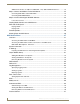
Table of Contents Table of Contents MAX Servers - Overview ....................................................................................1 Related Documents.................................................................................................................. 2 MAX HT Servers - Photos and Specifications ......................................................3 MAX-HT04/HT12 Home Theater Servers ........................................................................
Table of Contents Additional Information on USB Ports: MMS-04S, -12S, -900 and MAX-HT Servers.............. 24 Step 5: Connect the Modules To the MAX Server .......................................................... 24 Connecting MAX-AVPs and/or MAX-AVMs ........................................................................... 24 Connecting MAX-AOM Modules ............................................................................................ 25 Step 6: Install and Configure WinMAX Software.......
Table of Contents Online Tech Support ...................................................................................................... 41 Cover Art ......................................................................................................................... 42 Change Region ............................................................................................................... 42 Changing The Region Code Setting On Your MAX Server....................................................
Table of Contents Step 1: Prepare the Slide Rail Assemblies ............................................................................ 63 Step 2: Attach the Inner Server Rails to the MMS chassis .................................................... 63 Step 3: Attach the Extension Brackets to the Outer Rails...................................................... 63 Step 4: Install the Outer Rail/Extension Racket Assemblies In the Rack...............................
MAX Servers - Overview MAX Servers - Overview NOTICE: MAX Products are not designed or intended to, and may not be used to, violate anyone’s copyright or other intellectual property rights. Each user of the Products may only use the Products in connection with materials legally owned or licensed by such user and only to the extent such ownership or license rights permit such use.
MAX Servers - Overview HT Home Theater Servers MAX-HT04 (FG 2178-14) MAX-HT12 (FG 2178-15) more than 1TB of content storage more than 4TB of content storage FIG. 2 MAX HT Home Theater Servers Connect a PS/2 mouse and keyboard, and a VGA monitor directly to the MAX server to access the on-board interface, called the MAX Admin Menu. You’ll use the options in the Admin Menu to configure communication settings and add/remove MAX-AVM and MAXAOM modules.
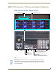
MAX HT Servers - Photos and Specifications MAX HT Servers - Photos and Specifications MAX-HT04/HT12 Home Theater Servers DVD/CDRW tray Storage Disc Drives Power ON/OFF toggle switch Master Power switch Power cable connector USB 1 port RS-232 VGA USB 2 port PS/2 keyboard & mouse ports ETHERNET CONTROL switched GB Control segment (to NetLinx Master or PC) A/V OUT switched GB Content segment (to MAX-AVMs and/or MAX-AVPs) FIG.
MAX HT Servers - Photos and Specifications Product Specifications MAX-HT04/HT12 Specifications Device Models: • MAX-HT04 (FG 2178-14) • MAX-HT12 (FG 2178-15) Storage Capacity: • MAX-HT04: 1.1 TBs, 275 DVDs (max) / 138 DVDs (min.) • MAX-HT12: 4.0 TBs, 1000 DVDs (max) / 500 DVDs (min.) Notes: • The MAX number of DVDs is based on DVDs at 4.0 GB. • The MIN number is based on the largest DVD at 8.0 GB. • DVD capacity is based on typical commercial DVDs.
MAX HT Servers - Photos and Specifications MAX-HT04/HT12 Specifications (Cont.) Operating Environment: • Operating Temperature: 10º to 35º C • Operating Relative Humidity: 20% to 80% (non-condensing) • Minimum Ventilation Clearance: 3" front and 3" rear Included Accessories: • One 6’ (1.
MAX HT Servers - Photos and Specifications 6 MAX Servers: HT Home Theater and MMS Multimedia Servers
MAX MMS Servers - Photos and Specifications MAX MMS Servers - Photos and Specifications MMS-01S Multimedia Server Faceplate snaps on/off to allow access to the hard drive and DVD/CDRW drive PS/2 keyboard & mouse ports USB port Power cable connector Master Power switch Power On/Off RS-232 (front) (Digital + Analog L/R) Audio Out 2 Audio Out 1 (rear) VGA A/V OUT switched GB Content segment (to MAX-AVM Modules) ETHERNET CONTROL switched GB Control segment (to NetLinx Master or PC) FIG.
MAX MMS Servers - Photos and Specifications MMS-01S (FG 2178-10) Product Specifications (Cont.) Rear Panel Components (Cont.
MAX MMS Servers - Photos and Specifications MMS-02S Multimedia Server Faceplate snaps on/off to allow access to the hard drive and DVD/CDRW drive PS/2 keyboard & mouse ports USB port Power cable connector Master Power switch Power On/Off RS-232 (front) (Digital + Analog L/R) Audio Out 2 Audio Out 1 (rear) VGA A/V OUT switched GB Content segment (to MAX-AVM Modules) ETHERNET CONTROL switched GB Control segment (to NetLinx Master or PC) FIG.
MAX MMS Servers - Photos and Specifications MMS-02S (FG 2178-12) Product Specifications (Cont.) Audio Output: • 2 audio output channels, each with RCA SPDIF digital, analog stereo • Digital audio output: 6-channel Dolby Digital and DTS • Analog audio output: stereo • 24-bit D/A conversion, 128X over sampling • 48kHz sampling rate • Output level -10dBV nominal • Signal to Noise Ratio 110db A-weighted • Frequency Response: 20Hz to 20kHz • Dynamic Range: 110dB Dimensions (HWD): (without rack ears) • 1.
MAX MMS Servers - Photos and Specifications MMS-02SB Multimedia Server with Backup Faceplate snaps on/off to allow access to the hard drive and DVD/CDRW drive Master Power switch Power On/Off (front) (Digital + Analog L/R) Audio Out 2 Audio Out 1 PS/2 keyboard & mouse ports USB port Power cable connector RS-232 (rear) VGA A/V OUT switched GB Content segment (to MAX-AVM Modules) ETHERNET CONTROL switched GB Control segment (to NetLinx Master or PC) FIG.
MAX MMS Servers - Photos and Specifications MMS-02SB (FG 2178-11) Product Specifications (Cont.) Audio Output: • 2 audio output channels, each with RCA SPDIF digital, analog stereo • Digital audio output: 6-channel Dolby Digital and DTS • Analog audio output: stereo • 24-bit D/A conversion, 128X over sampling • 48kHz sampling rate • Output level -10dBV nominal • Signal to Noise Ratio 110db A-weighted • Frequency Response: 20Hz to 20kHz • Dynamic Range: 110dB Dimensions (HWD): (without rack ears) • 1.
MAX MMS Servers - Photos and Specifications MMS-04S Multimedia Server Faceplate snaps on/off to allow access to the hard drive and DVD/CDRW drive (front) Power On/Off pushbutton Power cable connector PS/2 keyboard & mouse ports USB 2 port USB 1 port (rear) Master Power switch RS-232 VGA A/V OUT switched GB Content segment (to MAX-AVM Modules) ETHERNET CONTROL switched GB Control segment (to NetLinx Master or PC) FIG.
MAX MMS Servers - Photos and Specifications MMS-04S (FG 2178-07) Product Specifications (Cont.) Operating Environment: • Operating Temperature: 10º to 35º C • Operating Relative Humidity: 20% to 80% (non-condensing) • Minimum Ventilation Clearance: 3" front and 3" rear • Operating acoustic noise: 62 dBA Included Accessories: • One 6’ (1.
MAX MMS Servers - Photos and Specifications MMS-12S Multimedia Server Faceplate snaps on/off to allow access to the hard drives (front) 2 Power cable connectors 2 Removable power supplies Power Supply Reset PS/2 keyboard & mouse ports USB 2 port USB 1 port (rear) RS-232 Power On/Off VGA A/V OUT switched GB Content segment (to MAX-AVM Modules) ETHERNET CONTROL switched GB Control segment (to NetLinx Master or PC) FIG.
MAX MMS Servers - Photos and Specifications MMS-12S (FG 2178-08) Product Specifications (Cont.) Rear Panel Components (Cont.): • ETHERNET CONTROL port: RJ-45 Gigabit Ethernet port provides 1000/100/10 Mb/s network connectivity between the MMS and the NetLinx Master or PC • A/V OUT port: RJ-45 Gigabit Ethernet port provides 1000/100/10 Mb/s network connectivity between the MMS and MAX-AVM module(s) for A/V distribution Dimensions (HWD): (without rack ears) • 3.50”" x 17.3" x 20" (8.89 cm x 43.94 cm x 50.
MAX MMS Servers - Photos and Specifications MMS-900 Multimedia Server Reset button Storage Disc Drives Hard drive activity LEDs DVD/CDRW tray Power LED (green) Bootup Disc LED (yellow) Fan LED (red) Power button (front) ETHERNET CONTROL switched GB Control segment (to NetLinx Master or PC) PS/2 keyboard & mouse ports A/V OUT switched GB Content segment (to MAX-AVM Modules) USB 1 port USB 2 port RS-232 VGA (rear) 4 Power cable connectors FIG.
MAX MMS Servers - Photos and Specifications Product Specifications MMS-900 (FG 2178-06) Storage capacity: • Over 7 terabytes of storage space • 900 DVD (22,500 CD) capacity (approximate values) • Approximately 25 CDs can be stored in place of 1 DVD • Uses a RAID 5 disc drive system Power: • 115 VAC/950W • 3+1 redundant power supply • 350W per module AC Current Draw (AMP): For each of the 3 power supplies: • 8.84A - Bootup/Power Cycle Peak • 3.
MAX Servers - Setup and Configuration MAX Servers - Setup and Configuration Overview The following sections describe the basic process of setting up a MAX server and making the configurations required to get the server up and running with one or more MAX-AVP Audio/Video Players and/or MAX-AVM Audio/Video Modules and MAX-AOM Audio-Only (USB) modules. MAX-MMS Servers support up to 25 MAX-AVM modules and up to 2 MAX-AOM (USB) modules.
MAX Servers - Setup and Configuration Online Database MAX systems (firmware version 4.34 or higher) rely on an online media database for disc recognition. The online database provides all media information (such as disc title, track/chapter information, artist information, etc.). In order to identify discs (CDs and/or DVDs) as they are added to the MAX Server, the MAX Server must have permanent access to the internet.
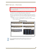
MAX Servers - Setup and Configuration Static electricity can damage electronic circuitry. Before touching the MAX server, discharge any accumulated static electricity from your body by touching a grounded metal object. Connect a PS/2 mouse and keyboard, and a VGA monitor directly to the MAX server to access the onboard interface, called the MAX Admin Menu (FIG. 12).
MAX Servers - Setup and Configuration Step 3: Access the MAX Admin Menu Once the boot-up process is complete, the MAX Admin Menu (FIG. 12) is displayed: FIG. 12 MAX Admin Menu The MAX Admin Menu allows access to various administrative functions for the MAX server. Working With the MAX Admin Menu Use the arrow keys on the keyboard to highlight the desired option, and press Enter to make a selection. Do not use the arrow keys on your keyboard’s numeric keypad.
MAX Servers - Setup and Configuration Note: The server will not allow you to assign a module to an output/zone that is already in use. Select Output Module Setup > View to review the current output/zone assignments. 3. In the Enter Serial Number field, enter the Setup Serial (Key) Number. This number is printed on a decal located on the bottom of each AVM/AVP enclosure. The system will notify you that the AVP (or AVM) has been added to the system.
MAX Servers - Setup and Configuration MMS Output/Zone (1-33) USB Port Connection (1 or 2) Audio Output (1-4) 1 1 1‘ 2 1 2 3 1 3 4 1 4 5 2 1 6 2 2 7...(to 33) AVM 3... Additional Information on USB Ports: MMS-04S, -12S, -900 and MAX-HT Servers If you are using both USB connectors on the MAX server, be sure to note which audio zones are associated with the AOM connected to each USB port: The USB 1 port is for audio zones 1 through 4. The USB 2 port is for audio zones 5 through 8.
MAX Servers - Setup and Configuration Connecting MAX-AOM Modules Do not use a USB hub with MAX-HT servers or AOM modules. 1. Connect the MAX-AOM(s) to an audio system (amplifier, switcher, etc.), using one of two options: a. Use RCA cables for analog stereo output (L and R) b. Use a coaxial cable for digital audio output (D) 2. Connect the included power supply to apply power to the AOM. 3. Use the supplied USB cable to connect the AOM module to a USB port on the server.
MAX Servers - Setup and Configuration You can also use WinMAX to establish a Telnet connection with the MAX to access the MAX Admin Menu: in the WinMAX System Information tab, click on Server Configuration. You will be prompted for a User Name and Password. These are case sensitive, and by default: User Name = root Password = mozart If you have connected directly to the MAX (as described in Step 1), you will not be prompted for a User Name or Password.
MAX Admin Menu MAX Admin Menu Overview MAX servers utilize a built-in interface called the MAX Admin Menu that allows access to various administrative functions for the MAX server. To access the MAX Admin Menu, you must establish a telnet session with the server. There are two ways to access the MAX Admin Menu - either via the Server Configuration option in WinMAX, or by connecting directly to the MAX server.
MAX Admin Menu 3. Click the Server Configuration button to open the MAX Server Configuration window and establish a telnet session with the server. 4. You will be prompted to enter a login ID and (Master) password. Once these have been entered correctly, the MAX Admin Menu is displayed in this window. Accessing the Admin Menu via Direct Connection to the MAX Server Alternatively, you can connect a mouse, keyboard and VGA monitor directly to the MAX server, via the connectors on the rear panel (FIG. 14).
MAX Admin Menu • Authenticate HDD: The options on this page allow you to add, remove and view hard disc drives (HDDs) in the MAX server. • Parental Control: This page allows you to enable parental control functionality. • Online Tech Support: This option allows you to establish a connection between the MAX server and AMX Technical Support, for remote troubleshooting and support operations. • Disconnect Support: Terminates the connection between the MAX server and AMX Technical Support.
MAX Admin Menu • Time: Current time (HH:MM:SS) • Time Zone: Local time zone. • Total Storage: Total amount of disc space available for content storage on this server. • Space Used: Total amount of disc space currently being used. • Available: Amount of disc space currently available for storage. • No. of CD’s: The number of audio CDs currently loaded in the server’s library. • No. of DVD’s: The number of DVDs currently loaded in the server’s library.
MAX Admin Menu FIG. 17 MAX Admin Menu - Configure TCP/IP Preparing the MAX Server for Receiving Periodic Updates The IP Settings (Gateway and Primary DNS) in the WinMAX Server Configuration screen must be set correctly. To prepare your server for automatic updates: 1. Connect your PC to the Internet and open the WinMAX software. 2. Go to an MS-DOS Command Prompt on your PC and type ipconfig /all then press Enter. Note the Default Gateway and first DNS Server settings. 3.
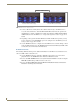
MAX Admin Menu MAX-HT Home Theater Servers treat MAX-AVP Audio-Video Players exactly the same as MAX-AVP modules, and the process of adding AVPs is the same as that for AVPs. MAX-AVPs are supported by HT servers only - they are not supported by MMS servers. Adding New Modules to the System 1. Select Add, then select the type of module (MAX-AOM or MAX-AVM) you are adding (FIG. 19). FIG.
MAX Admin Menu Viewing all Modules in the System Select View in the Output Module Setup page (FIG. 18) to open a read-only list of all modules currently detected by the server to be installed in the system (FIG. 21). FIG. 21 Installed Output Modules Removing Modules From the System Select Remove in the Output Module Setup page (FIG. 18) to open a list of all modules currently installed in the system. To remove one or modules from the system.
MAX Admin Menu FIG. 23 MAX Admin Menu - RAID 5 Status RAID 5 CLI This set of options rebuilds the server’s RAID array. This option is only for use by AMX Technical Support. If the RAID array is rebuilt, all content on the server will be lost and the unit be rendered inoperable.
MAX Admin Menu Log Management FIG. 24 MAX Admin Menu - Log Management MAX Servers have the ability to log various internal activities, primarily for troubleshooting purposes. The options on this page allow you to view and delete log files, and control the logging level for the server. Specifying Logging Levels Select Log Toggles in the Log Management menu to access the Select Log Options menu (FIG. 25), where you can select which events to include in the logs (RS232, ADA, TCP/IP, and DEBUG). FIG.
MAX Admin Menu FIG. 26 Example of a log display Deleting Log Files Select Delete Log Files from the Log Management menu. The system will prompt you to verify this action before the files are erased. Date, Time Locale This set of options allows you to specify/adjust the system’s date, time and location settings (FIG. 27). FIG.
MAX Admin Menu Setting System Date and Time When you select Date, Time, Locale from the MAX Admin Menu, a wizard is invoked which steps you through the process of setting the date and time for the system: 1. The first screen to appear is the Configure Timezones screen (FIG. 28). FIG. 28 Date, Time, Locale - Configure Timezones 2. Select wether to set the hardware clock to GMT (Greenwich Mean Time).
MAX Admin Menu 5. Click OK to proceed to the Set New Time screen (FIG. 30), where you can set the system time (in HH:MM:SS format). To adjust the time settings, move the highlighted cursor to the time field that you want to adjust and use the up and down arrow keys to adjust the value up or down. FIG. 30 Date, Time, Locale - Set New Time 6. Click OK to proceed to the final screen which displays the new Date and Time settings (FIG. 31). Click OK to save your changes and return to the MAX Admin Menu. FIG.
MAX Admin Menu Authenticate HDD The set of options on this page allow you to add, remove and view hard disc drives (HDDs) in the MAX server (FIG. 33). FIG. 33 MAX Admin Menu - Authenticate HDD For detailed instructions on replacing HDDs in MAX Servers, refer to the Replacing HDDs in MAX Servers section on page 51. The options in the Authenticate HDD menu include: Add: Select to authenticate a new HDD, as described in the previous section.
MAX Admin Menu FIG. 34 Admin Menu, Authenticate HDD, and Add HDD dialogs Viewing All HDDs In the MAX Server Select View from the Authenticate HDD menu to view all the serial numbers and keys for HDDs in the system (FIG. 35). Note that this list only indicates HDDs that have been successfully authenticated. FIG. 35 Authenticate Menu - View HDD Removing HDDs From the MAX Server Select Remove from the Authenticate HDD menu to remove a selected HDD from the system.
MAX Admin Menu Parental Control FIG. 37 MAX Admin Menu - Parental Control This page allows you to enable parental control functionality. To enable parental control, enter a new parental control password and select OK. Online Tech Support FIG. 38 MAX Admin Menu - Online Tech Support This option allows you to establish a connection between the MAX server and AMX Technical Support, for remote troubleshooting and support operations.
MAX Admin Menu Cover Art This option retrieves updated cover art for discs in the MAX server’s media library. Change Region The information in this document concerning region code settings does not apply to the MMS-12S Server, since the MMS-12S does not feature a DVD-ROM drive. The region code setting for the MAX Server’s internal DVD-ROM drive must match the region code of the DVD(s) you are attempting to load.
MAX Admin Menu code setting (keeping in mind that it can only be changed a maximum of five times). Also, insure that the last region code setting made matches the region in which the MAX will be installed. Changing The Region Code Setting On Your MAX Server 1. 2. 3. 4. 5. Insert a DVD with your local region coding in the MAX Server’s DVD-ROM drive. In the System Information tab, click the Server Configuration button to access the Admin Menu.
MAX Admin Menu FIG. 41 Update Firmware > Schedule > Day of Week and Select Time options Manually Updating the Firmware Select Update from the Update Firmware page (FIG. 40) to manually check for firmware updates for the server. If an update is detected, it is automatically downloaded and installed. Restart MAX deamon This option restarts the MAX daemon. Restart the daemon to activate any configuration changes made via the options in the MAX Admin menu. Shutdown FIG.
DVD Region Code Settings DVD Region Code Settings Overview All DVD players and most DVD discs are labeled for operation within a specific geographical region in the world. This is know as a Region Code. DVD discs are encoded for a specific region, and must match the region code of the physical DVD drive to be played. Region code recognition only applies to the physical DVD disc and the physical DVDROM drive. For example, the U.S. is in Region 1. This means that all DVD players sold in the U.S.
DVD Region Code Settings Default Region Code Setting By default, the MAX Server’s DVD-ROM drives are set to read DVDs with Region 1 encoding (for U.S., Canada and U.S. Territories). Depending on what region of the world you are installing and operating the MAX, you may need to change the region code setting in order to read DVDs. There are three sources used for loading content onto a MAX server: 1. MDL200 with BulkRipper software running on Windows PC. 2.
DVD Region Code Settings The number of region code setting resets still available is indicated here (Max resets = 5). FIG. 43 MAX Admin Menu - Change Region You can change the region code setting on your MAX Server’s DVD-ROM drive up to five times, and no more. The region code setting is locked down in the DVD-ROM drive the fifth time it is set, permanently setting to that last region code setting. At that point there is no way to change the region code setting again.
DVD Region Code Settings 48 MAX Servers: HT Home Theater and MMS Multimedia Servers
MAX Servers DVD Drives - Supported Formats MAX Servers DVD Drives - Supported Formats DVD Drives - Compatible Formats The following tables indicate the compatibility of several common DVD Drives used in MAX Servers, relative to DVD formats: DVD Drives - Compatible Formats Drive Model DVD-ROM DVD-R DVD-RW X Panasonic CW-8124-B DVD+R DVD+RW X X Plextor PX-504A X X X X Plextor PX-708A X X X X X X DVD-RAM DVD+R DL DVD±RW X Sony CRX820E Sony CRX835E Sony CRX850E X X X X Toshiba SD
MAX Servers DVD Drives - Supported Formats MDL Series - DVD Drives The following table indicates the compatibilities of the DVD Drives in the MDL Series (Powerfile): MDL Series (PowerFile) - DVD Drives 50 C200ROM and C200 • DVD-ROM, DVD-R R200ROM • DVD-ROM, DVD-R, DVD-RW, DVD+R, DVD+RW, DVD-RAM,DVD+/-RW R200ROM • Reads all formats listed above MAX Servers: HT Home Theater and MMS Multimedia Servers
Replacing HDDs in MAX Servers Replacing HDDs in MAX Servers Overview MAX MMS and HT servers support hot-swappable hard disk drives (HDDs), accessible behind the removable faceplate, on the front panel. Typically a new HDD will be required only if an existing one has failed. The MMS-01S, MMS-02S, MMS-04S and MMS-12S servers all utilize 250GB hard drives, and require the MMS-HDD250G 250GB drive (FG 2178-250) for replacements.
Replacing HDDs in MAX Servers Don’t forget to include the port number. If you are using Mozilla as your browser, you’ll need to override the security that blocks port 1080. To unblock port 1080, add the following line (located at /usr/lib/ mozilla/defaults/pref/all.js): pref(“network.security.ports.banned.override”,”1080”) 3. Press Enter to open the Disk Management Utility - Home Page (FIG. 44). FIG. 44 Disk Management Utility - Home page 4.
Replacing HDDs in MAX Servers Degraded FIG. 45 Disk Management Utility - Configure page 5. Note the Port Number of the Degraded drive, and determine which physical drive needs to be replaced in the server: For MMS servers, refer to the charts in FIG.
Replacing HDDs in MAX Servers Also note that the LED on the degraded drive should blink to indicate that it needs to be replaced. Once you have determined which drive needs to be replaced, you can proceed to physically removing the bad drive, and installing the replacement drive.
Replacing HDDs in MAX Servers 5. Check the box next to the failed drive that you are removing, and click the Remove Drive button at the bottom of the screen. 6. Check the box again and click the Add Drive button at the bottom of the page. 7. Check all boxes next to all the drives (only in the array that contains the replaced HDD). 8. Check the Force Continue On Source Errors checkbox at the bottom of the screen. 9. Click the Rebuild Unit button.
Replacing HDDs in MAX Servers FIG. 48 Admin Menu, Authenticate HDD, and Add HDD dialogs Replacing HDDs in HT Servers The AMX line of MAX HT servers support hot-swappable 400GB hard disk drives (HDDs), accessible behind the faceplate on the front panel (FIG. 49). Typically a new HDD will be required only if an existing one has failed. FIG. 49 MAX-HT12 Server (front panel) Replacement HDDs are available from AMX (FG 2178-400).
Replacing HDDs in MAX Servers Step 1: Identify the Drive That Needs To Be Replaced To identify the drive that needs to be replaced, access the MAX Admin Menu, via Telnet: 1. Launch WinMAX, open the System Information tab, and verify that you are communicating with the intended HT server by checking the Server IP Address or URL field. 2. Click on the Server Configuration button to open a telnet window. After a brief delay, the system prompts you to log in.
Replacing HDDs in MAX Servers 1 Pull the latch forward to unlock the drive tray 2 Carefully slide the drive/tray assembly out of its slot. Drive number (silk-screen) FIG. 51 Removable drive/tray assembly (front panel) 3. Install and secure the replacement drive into the drive tray. 4. Slide the replacement drive/tray assembly fully into the slot, and push the hinged latch back into its locked position.
Replacing HDDs in MAX Servers MAX Admin Menu Use the other options in the Authenticate HDD menu (accessible via the Admin Menu on the MMS), to manage all HDDs in the server, as shown in FIG. 48. FIG. 52 Authenticate Menu - View HDD and Select HDD(s) to Remove dialogs The options in the Authenticate HDD menu are described below: • Add: Select to authenticate a new HDD, as described in the previous section. • View: Select to view all the serial numbers and keys for HDDs in the system.
Replacing HDDs in MAX Servers 60 MAX Servers: HT Home Theater and MMS Multimedia Servers
Rack Mounting MAX Servers Rack Mounting MAX Servers CAUTION: Safety Instructions Use the following safety guidelines to help ensure your own personal safety and to help protect your system and working environment from potential damage. Installing systems in a rack without the front and side stabilizers installed could cause the rack to tip over, potentially resulting in bodily injury under certain circumstances. Therefore, always install the stabilizers before installing components in the rack.
Rack Mounting MAX Servers Rack Mounting MMS-01S/02S/02SB/04S/12S Servers MMS-01S, -02S, -02SB, -04S and -12S servers come with a Rack-Mounting Kit, which includes the hardware required to mount the servers in a standard 19-inch (48-cm) rack. MMS-900 Servers use a more heavy-duty version of the installation kit to accommodate their size and weight. The Rack-Mounting Kit that comes with the MMS-900 comes with its own installation instructions.
Rack Mounting MAX Servers Step 1: Prepare the Slide Rail Assemblies The two Outer Slide Rails, and two Inner Server Rails come assembled in the rack rail hardware kit. You must separate these pieces before beginning. The Inner Server Rails will be attached to the MMS chassis. To detach the server rails from the slide rail assemblies: 1. Place the two slide rail assemblies on a flat surface. 2.
Rack Mounting MAX Servers Extension Bracket Feet Outer Rail front Locking plate Extension bracket FIG. 55 Attaching the Extension Bracket to the Outer Rail (using a Locking Plate) Step 4: Install the Outer Rail/Extension Racket Assemblies In the Rack Once both of the Outer Rail/Bracket assembles (from the previous step) are prepared, they can be installed into the rack cabinet. Follow these steps for both of the Outer Rail/Bracket assemblies: 1. Insert the Outer Rail/Bracket assembly into the rack.
Rack Mounting MAX Servers Inner Server Rail Outer Slide Rail Extension Bracket Rack (front) FIG. 56 Sliding the MMS server chassis into the rack Rack Mounting HT and MMS-900 Servers Each MAX-HT server comes with a Rack-Mounting Kit. Each Rack-Mounting Kit supports one server and includes all hardware required to mount HT servers in a standard 19-inch (48-cm) equipment rack.
Rack Mounting MAX Servers You may not need all the parts included in the kit for every installation. Before you begin, disassemble the Slide Rail Assemblies: the Stationary, Intermediate and Chassis sections must be separated before they can be attached to the server and rack. CAUTION: Safety Instructions Use the following safety guidelines to help ensure your own personal safety and to help protect your system and working environment from potential damage.
Rack Mounting MAX Servers (rear) (front) HT Server chassis Chassis Sections The Locking Tab on each Chassis Section should be oriented towards the rear of the server FIG. 58 Attaching the Chassis Sections to the server chassis Step 2: Slide Intermediate Sections Into the Stationary Sections 1. Slide the Intermediate Section into the Stationary Section, from the rear end of the Stationary Section, as shown in FIG. 59. 2.
Rack Mounting MAX Servers Step 3: Attach the Extension Brackets With the Intermediate and Stationary Sections together, you can now attach the Extension Brackets. The Extension Brackets attach to the rear end of the Stationary Section, and allow the Rail Assembly to be anchored to the rear of the equipment rack. Note that the Extension Brackets are designed to accommodate a range of depths.
Rack Mounting MAX Servers FRONT VIEW REAR VIEW The bottom of the Adapter Bar sits flush against the tabs on the Rack-Rail assembly Use these holes to mount the Adapter Bar to the Rack-Rails Use the outside and center holes to mount the Rack-Rail w/ Adapter Bars to the equipment rack FIG. 61 Adapter Bar mounted to the front of the Rack-Rail assembly 2. Attach an Adapter Bar to the rear of each of the two Rack-Rail assemblies (FIG. 62).
Rack Mounting MAX Servers Mounting Rail in equipment rack Adapter Bar Align the top hole on the Adapter Bar to the bottom hole of the upper-adjacent RU in the equipment rack. Align the center hole on the Adapter Bar to a center hole in one of the RUs in the equipment rack. Align the bottom hole on the Adapter Bar to the top hole of the lower-adjacent RU in the equipment rack. FIG. 63 Align the holes on the Adapter Bar to the holes on the rails in the equipment rack FIG.
Rack Mounting MAX Servers 4. Carefully slide the server into the rack until the Locking Release Tabs on the Chassis Sections (in the equipment rack) engage the Intermediate Section Rails, securing the server in place. Equipment Rack Intermediate Section (fully extended) Chassis Section CAUTION! Refer to the Safety Instructions on page one before installing the server chassis into the equipment rack FIG.
Rack Mounting MAX Servers 72 MAX Servers: HT Home Theater and MMS Multimedia Servers
Rack Mounting MAX Servers MAX Servers: HT Home Theater and MMS Multimedia Servers 73
9/07 ©2007 AMX. All rights reserved. AMX and the AMX logo are registered trademarks of AMX. AMX reserves the right to alter specifications without notice at any time. It’s Your World - Take Control™ 3000 RESEARCH DRIVE, RICHARDSON, TX 75082 USA • 800.222.0193 • 469.624.8000 • 469-624-7153 fax • 800.932.6993 technical support • www.amx.