Operation/Reference Guide MVP-KS Kickstand for MVP-7500/8400 Modero® ViewPoint® Wireless Touch Panels Touch Panels & Accessories Last Revised: 10/06/2006
AMX Limited Warranty and Disclaimer AMX warrants its products to be free of defects in material and workmanship under normal use for three (3) years from the date of purchase from AMX, with the following exceptions: • Electroluminescent and LCD Control Panels are warranted for three (3) years, except for the display and touch overlay components that are warranted for a period of one (1) year.
FCC Information This device complies with Part 15 of the FCC Rules. Operation is subject to the following two conditions: (1) this device may not cause harmful interference, and (2) this device must accept any interference received; including interference that may cause undesired operation. Federal Communications Commission (FCC) Statement This equipment has been tested and found to comply with the limits for a Class B digital device, pursuant to Part 15 of the FCC rules.
Table of Contents Table of Contents MVP-KS Kickstand ..............................................................................................1 Overview .................................................................................................................. 1 Specifications ................................................................................................................ 1 Securing an MVP Panel to an MVP-KS .......................................................................
Table of Contents ii MVP-KS Kickstand for MVP Panels
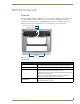
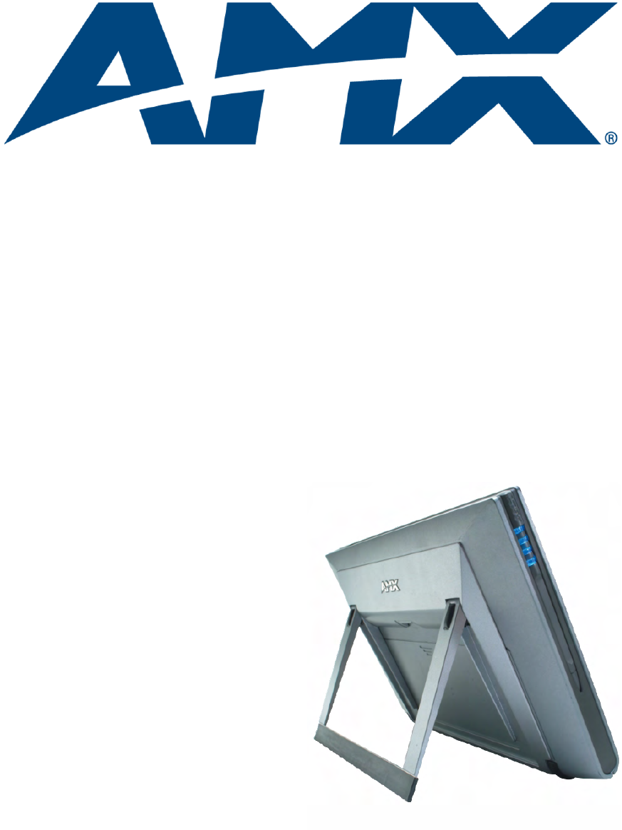
MVP-KS Kickstand MVP-KS Kickstand Overview The optional MVP-KS Kickstand (FG5965-12) is compatible with both MVP touch panel models and provides the ability to easily rest an MVP on any flat or level surface. The kickstand’s rubber grip provides traction on smooth surfaces. The MVP-KS mounts to the rear of the MVP by using a set of alignment guide pins and a retractable latch to secure the kickstand to the rear of the panel. MVP latch release lever Retractable latch Support arm Alignment guide pins FIG.
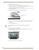
MVP-KS Kickstand Securing an MVP Panel to an MVP-KS 1. Place the MVP face down and locate the MVP-KS alignment guide pins (FIG. 1). These pins are inserted into the respective MVP alignment guide insertion holes (located along the underside of the MVP and at either sides of the connector strip). 2. Grasp both sides of the kickstand and insert the alignment guide pins into the insertion holes on the bottom of the MVP (FIG. 1). 3. Maintain a kickstand connection to the bottom of the MVP panel (FIG. 2).
MVP-KS Kickstand MVP-KS Kickstand for MVP Panels 3
AMX. All rights reserved. AMX and the AMX logo are registered trademarks of AMX. AMX reserves the right to alter specifications without notice at any time. ©2006 10/06 It’s Your World - Take Control™ 3000 RESEARCH DRIVE, RICHARDSON, TX 75082 USA • 800.222.0193 • 469.624.8000 • 469-624-7153 fax • 800.932.6993 technical support • www.amx.